DefineDC
Symbol | 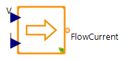 |
|---|
Use
This auxiliary interface model enables modelers to divide physical models with electric circuits at DC level into several parts and to freely cut individual electric branches. It often works in combination with the ExtractDC model.
The DefineDC covers the following applications:
Basic: During debugging, test simulations should show if parts of an electric circuit work properly, e.g. battery storage system with connected DCGrid but without a suitable power supplier. It therefore provides to add generic input data without closed-loop dependencies to other model components.
Advanced: Users want to integrate measured voltages and currents in an electric circuit as input data sets to a complex model - Hybrid Digital Twin. It provides an input interface for external data sets.
To use this model, connect suitable model components of the MSL (i.e. elements with real outputs of Modelica.Blocks like RealExpression or CombiTable1Ds) to define both ▶V and ▶I. Make sure that input values fit SI-units or similar units are used.