HeatController
Symbol | 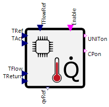 |
|---|
Use
The HeatController controls a heat generator such as a heat pump or a gas boiler. It ensures that the specified temperature is reached. This setpoint can be the desired room temperature or a desired storage tank temperature.
The HeatController covers the following applications:
Basic: The HeatController provides the generator with a switch-on and switch-off signal as well as the flow rate of the circulation pumps, i.e. the generator is either on at full power or completely off. The flow rate of the circulation pumps is controlled using a flow setpoint temperature.
Modulation: The output of the generator is additionally modulated, i.e. the generator is not only switched on and off, but can also only call up part of its maximum output during operation.
Cascade: This assumes that the generator has several generator stages (e.g. in the case of a heat pump compressors) or that there is a cascade of generators. These are used one after the other depending on the power requirement .
Heat Pump: If the generator is a heat pump, the HeatController must also take into account and control the source side of the heat pump , i.e. the HeatController not only regulates the volume flow on the heat sink side of the heat pump, but also the volume flow on the source side.
Auxiliary Heat Power Supply: If the heat generator requires an additional heat supply (e.g. additional heating element for a heat pump in winter), this can also be controlled via the HeatController.
Parameters and Connectors
Basic
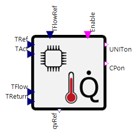
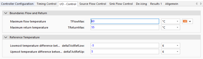
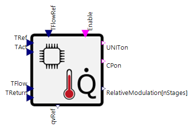
The controller requires the setpoint temperature specification (▶TRef) and the actual value (▶TAct) of the temperature to which is to be regulated. If the actual value falls below the setpoint by the difference of deltaTActRefLow, the generator is switched on (▶UNITon). If the actual value is above the setpoint by the difference deltaTActRefUp, the generator is switched off. In addition, the flow temperature (▶TFlow) and the return temperature (▶TReturn) are required at the generator in order to switch off the generator (emergency shutdown) if limit values (limit parameters TFlowMax and TReturnMax) are exceeded.
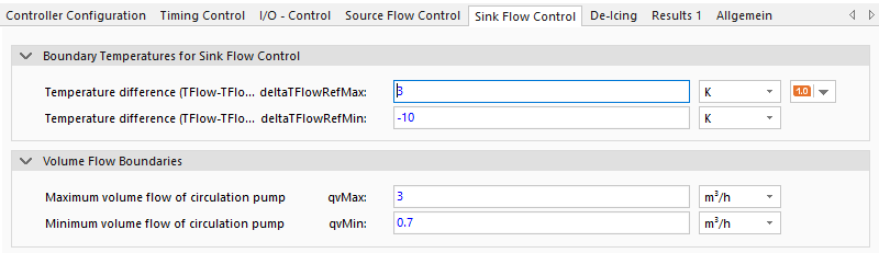
In addition, a specification for the desired flow temperature (▶TFlowRef) is required to determine the volume flow from the generator to the heat sink (volume flow of the circulation pumps - ▶qvRef) . This is regulated in the limits qvMax and qvMin using the difference between the actual flow temperature and the set flow temperature as well as the temperature limits deltaTFlowRefMax and deltaTFlowRefMin. In addition, a Boolean signal is provided via the output ▶CPon to control the pumps.
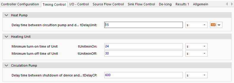
Delays (tDelayUnit and tDelayCP) are set between switching the circulation pumps and the generator on and off in order to prevent excessively high temperatures in the generator and the resulting switch-off. In addition, minimum switch-on and switch-off times (tUnitminOn, tUnitminOff) of the generator are defined to prevent excessive clocking of the generator.
The ▶Enable input can be used for the targeted switch-off of the generator by a higher-level control system, seasonal releases or similar.
Modulation
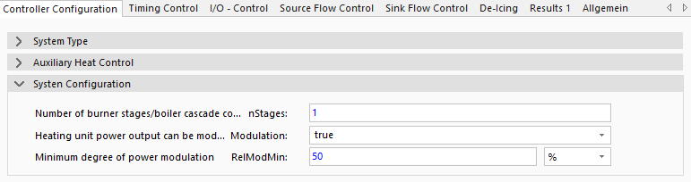
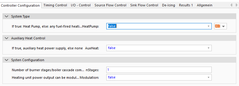
The Modulation parameter allows the generator not only to be switched on and off, but also to only call up part of its maximum output during operation. The technologically defined minimum modulation is mapped by the parameter RelModMin. The power is adjusted within the limits (deltaTModUp, deltaTModDown) using the actual and setpoint temperature and provided to the generator via the available connector (▶RelativeModulation) for connection. It is recommended that the temperature limits for switching on and off (deltaTFlowRefMax and deltaTFlowRefMin) are greater than or equal to the limits of the modulation. Otherwise the generator will be switched on or off before the modulation limits are reached.
Cascade
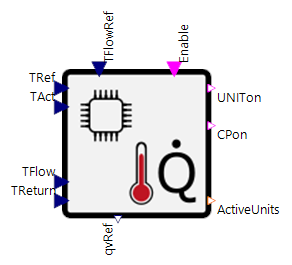
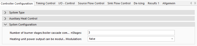
The nStages parameter can be used to control several (burner or compressor) stages of the heat generator or a cascade of generators. The ▶ActiveUnits connector is used for this purpose. Here too, the limits for the next stage (deltaTPrevStage, deltaTNextStage) should be smaller than the limits for switching the generator on and off in order to enable meaningful control. If modulation is also active, the limits for the next stage should be greater than the limits for modulation so that a stage or a generator from the cascade is fully utilised first. The following hierarchy is therefore recommended:
Reference temperature (deltaTActRef) > Stages (deltaTStage) > Modulation (deltaTMod)
The tUnitStateChange parameter can be used to specify the time that must elapse before the next change of the stage takes place. This should be adapted to the inertia of the actual temperature.
Heat Pump
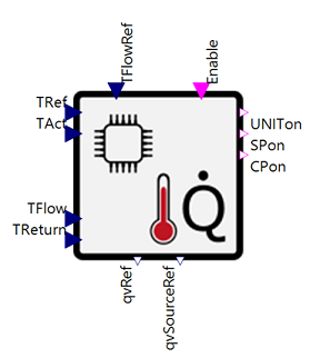
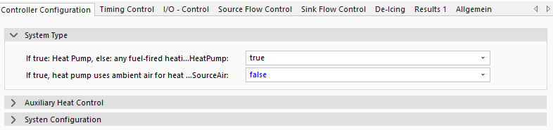
If the generator is a heat pump, the HeatPump parameter can be set to true. This enables connectors for controlling the pump(s) on the source side of the heat pump (▶SPon and ▶qvSourceRef in the image above). When the heat pump is switched on by the controller, a switch-on signal for the source pump is also output (▶SPon). In this case, the pump setpoint volume flow ▶qvSourceRef for the source pump corresponds to the constant value of the parameter qvSource (uncontrolled).
As with the circulation pump on the heat sink side, the tDelaySP and tDelaySPComp parameters are used to ensure a run-up or run-down of the source pump to the heat pump.
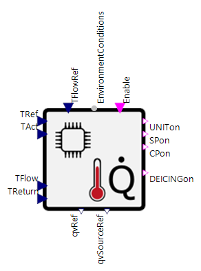
If the generator is an air heat pump (ambient air as the source), the parameter SourceAir can be set to true and the environment connector can be connected. In this way, the controller can also control the de-icing of the outdoor unit (▶DEICINGon) in winter. This assumes that de-icing is necessary at regular intervals (tOperation) from a limit temperature (TDeIcingBound). The de-icing itself is described with a duration of the process (tDeIcing) as well as a start-up (tDeIcingOn) and expiry time (tDeIcingOff).
Auxiliary Heat Power Supply
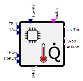
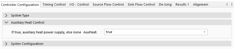
If there is another heat supply in addition to the generator (e.g. electric heating element for a heat pump), then the AuxHeat parameter can be set to true and this can also be controlled via the HeatController. In this case, it is controlled via the ▶AUXon connector using the temperature differences (deltaTAuxRefUp and deltaTAuxRefDown) and the delay (tBivalence - minimum duration of temperature undershoot) switched on or off.
Model Background
Volume Flow Control
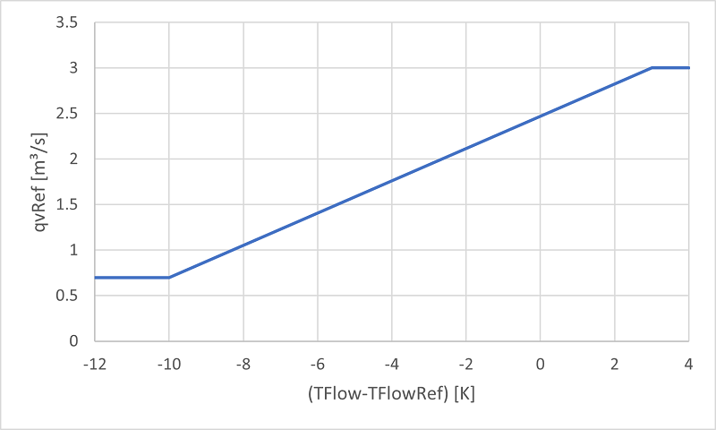
The volume flow of the circulation pump is defined by a linear approach as shown in the following figure. The decisive factor is the temperature difference between ▶TFlow and ▶TFlowRef. At the value deltaTFlowRefMax (in the image 3 K) the maximum volume flow qvMax is assumed to reduce the temperature stroke inside the generator. At the temperature difference deltaTFlowRefMin (in the image -10 K) the minimum volume flow qvMin is used to higher the temperature stroke. Linear interpolation takes place between the extreme values in order to achieve the desired set flow temperature ▶TFlowRef.
Calculation of Modulation
The modulation of the generator is determined using the following formula. In the case of a multi-stage generator, all stages have the same modulation.
Switch on/off
The switching on and off of the generator, the stages and the auxiliary heating is controlled via a hysteresis with the specified upper and lower limits of the temperature difference between setpoint and actual temperature.
Pre- and Post-run Time of Pumps
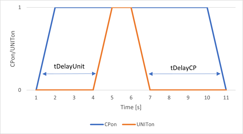
The logic of the time delay can be seen in the following figure. The UNIT (▶UNITon) is only switched on after the circulation pump is switched on and the time tDelayUnit (3 seconds in the figure) has elapsed. The logic for tDelayCP is analogue. This results in the ▶UNITon signal being switched on at 4 s after the circulation pump is switched on at time step 1 s. The circulation pump is then switched off 4 s (tDelayCP) after the unit is switched off.
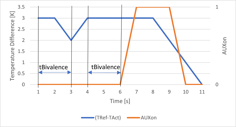
Prevention of Continuous Switching
The following illustration shows how the tBivalence parameter works. In this case, it is assumed that the switch-on limit (deltaTAuxRefDown) for the auxiliary heating is 3 Kelvin and the switch-off limit (deltaTAuxRefUp) is 1 Kelvin. This temperature difference is calculated by TRef-TAct. The image shows that the switch-on limit must be reached for at least the duration tBivalence (here 2 seconds) . If the temperature difference decreases within this period (as in the first case at time 3 s), no switch-on signal is issued. The auxiliary heating is only switched on when the temperature difference is reached for a full 2 seconds period (in the image at time 6 s). ▶AUXon is then switched off when the temperature falls below the lower temperature limit at time 10 s.