HeatExchanger
Symbol | 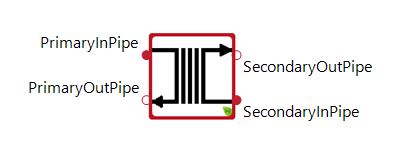 |
|---|
Use
The heat exchanger component represents a heat exchanger that is often used for the hydraulic decoupling of systems and, for example, for separating a brine circuit from circuits containing pure water.
Parameters and Connectors
The two circuits must be connected via the ▶PrimaryInPipe, ▶PrimaryOutPipe, ▶SecondaryInPipe and ▶SecondaryOutPipe.
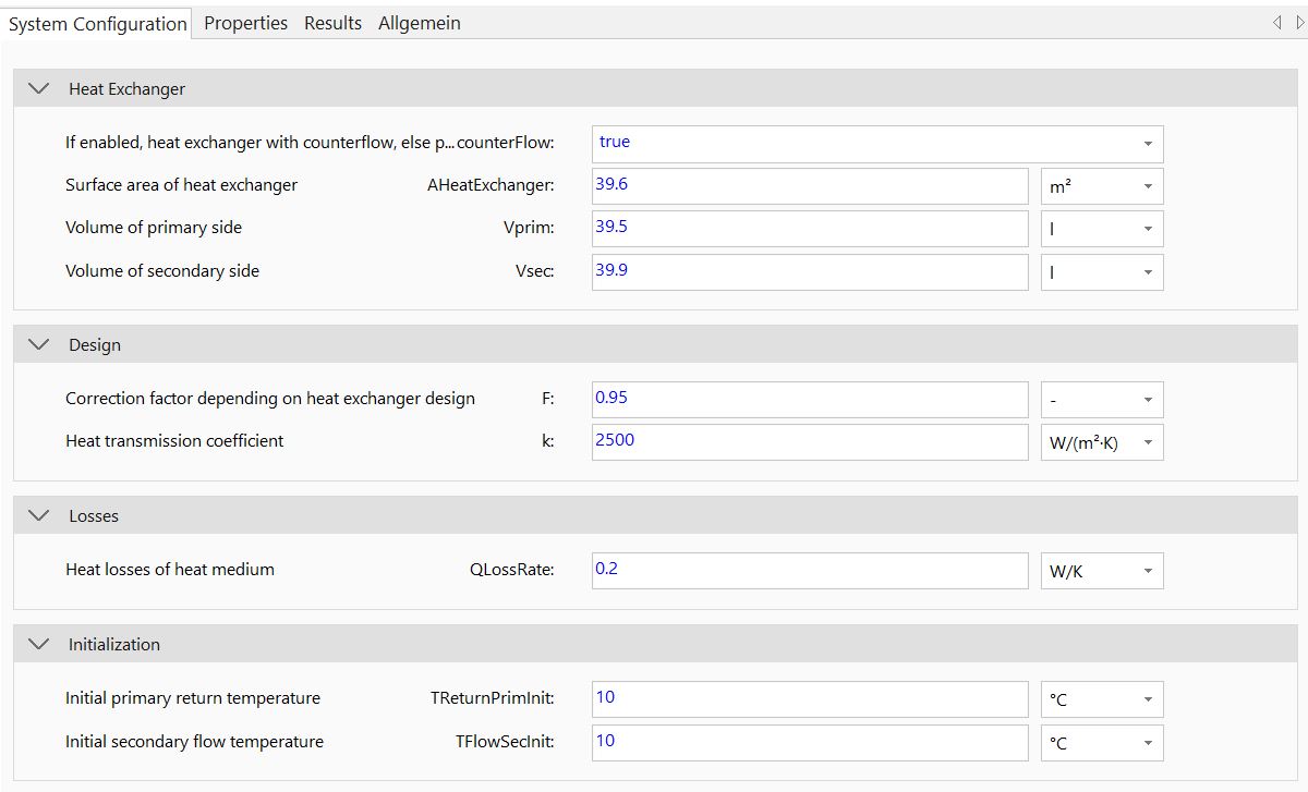
The heat power transferred between the two circuits depends on the effective heat transfer area (AHeatExchanger) and the correction (F) and transfer coefficients (k), as well as on the flow direction of the media (counterFlow). These are standard parameters that are specified in the heat exchanger data sheets.
The media volumes on the primary (Vprim) and secondary (Vsec) sides influence the thermal inertia of the element and must therefore be specified in the parameter dialog. The parameters TReturnPrimInit and TFlowSecInit are available to initialize the temperatures on both sides.
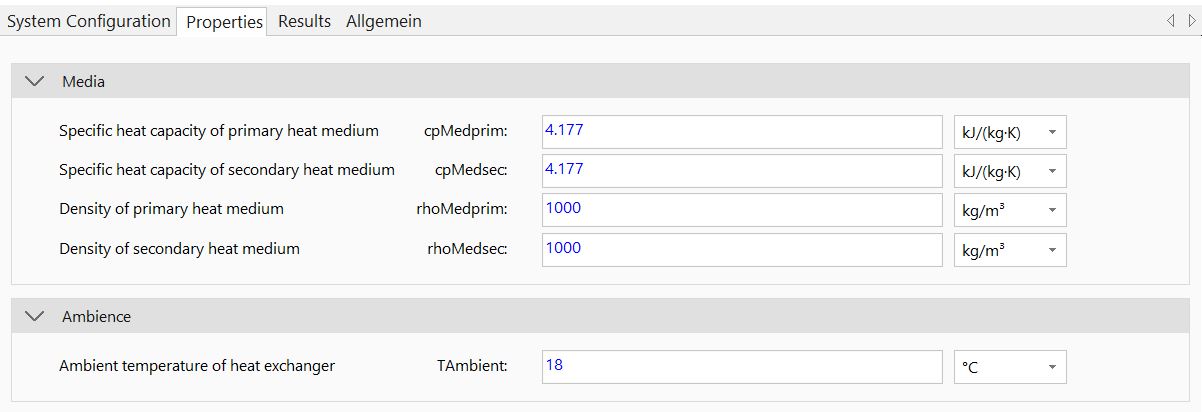
The different properties of the media on the primary (cpMedprim, rhoMedprim) and secondary (cpMedsec, rhoMedsec) sides must also be specified. Note that the QLossRate parameter can be used to approximate the heat loss to the environment specified by TAmbient.
Model Background
The heat exchanger model uses the Number of Units (NTU) method to simulate plate or tube heat exchangers in counter or parallel flow design.