HeatStorage
Symbol |  |
|---|
Use
The HeatStorage models sensitive heat storage (fluids without phase transition) with all heat flows and losses in an insulated or non-insulated cylindrical container. Typical applications for the HeatStorage are the buffer storage of heat from generators for a more even operation of the generators, the mixture of fluid flows of different temperatures or the temporal shift of renewable heat generation to times with a heat demand. The HeatStorage is functionally identical to the ColdStorage and only represents a visual differentiation for cold and hot fluid storage systems.
The HeatStorage covers the following applications:
Basic: The HeatStorage is charged or discharged via fluid flows and the associated heat flows. In addition, heat is exchanged between the individual heat layers within the HeatStorage and heat is exchanged with an isothermal environment.
Environment: Heat is exchanged with the environment, which has the same temperature as the air at the respective location.
Heat exchanger: In addition to charging/discharging the HeatStorage via the fluid flows, the heat flows in the HeatStorage can be controlled via one or more heat exchangers.
Parameters and Connectors
Basic
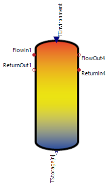
In its basic version, the HeatStorage uses a constant temperature input ▶TEnvironment, which is used to calculate the heat loss of the storage to its environment. ▶TStorage[n] returns the temperatures of all storage layers within the HeatStorage. ▶FlowIn1, ▶ReturnOut1, ▶FlowOut4, ▶ReturnIn4 are the storage connections for charging or discharging the HeatStorage. To activate the storage connections (▶FlowIn1, ▶ReturnOut1, ▶FlowOut4, ▶ReturnIn4, ...), the parameters (use1, use2, ...) must be set to true in one of the tabs of the pipes.
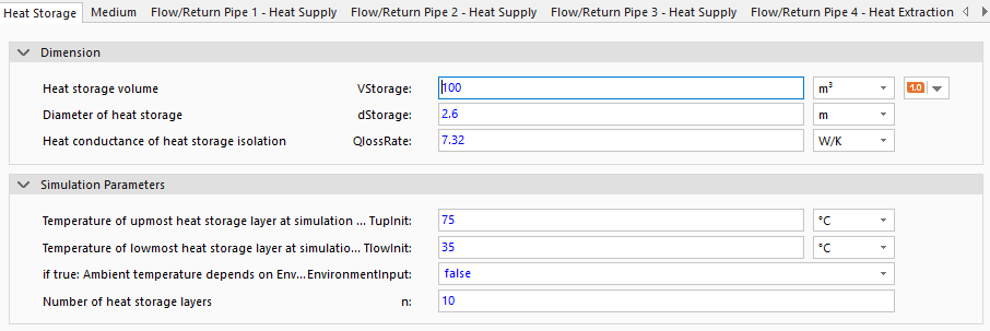
The most important technical parameters must be specified for dimensioning the HeatStorage. Based on the assumption that the HeatStorage is a cylindrical store, the parameters storage volume (VStorage), the storage diameter (dStorage) and the heat loss rate of the insulation (QlossRate) are specified for the geometric dimensioning. The storage volume (VStorage) is required as a parameter for the capacity of the HeatStorage, while the storage diameter (dStorage) together with the heat loss rate (QlossRate) are a measure of the heat losses to the environment.
The parameters in the Simulation Parameters group (see the figure) are used for more precise control of the simulation initialization or the model calculations. TupInit and TlowInit determine the start temperatures for the upper and lower storage tank temperature at the start of the simulation. If these temperatures are not known at the time of modeling , these parameters can be left at the default values. In this case, it should only be noted that the model requires a longer period of time to settle and provide more precise information. The parameter n determines the number of temperature layers within the memory and can be set as required (number 1 is the bottom layer and number n is the top layer). For a faster simulation, this parameter should have a value between 3-10.
EnvironmentInput is dealt with in the next section Environment.
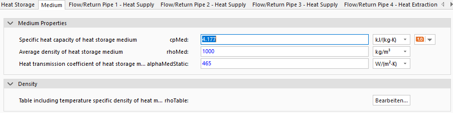
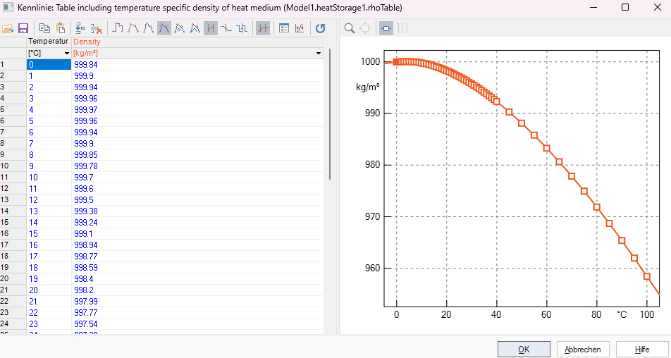
The parameters of the fluid within the heat storage are set under the Medium tab. This requires the parameters average specific heat capacity of the medium during operation (cpMed), the heat transfer coefficient between the heat storage temperature layers (alphaMedStatic) and the density of the medium as a function of the fluid temperature (rhoTable). The material values can be taken from standard books or other sources. Only one medium can be used at a time as it is not possible to mix different fluids (the default setting is water). For the setting of alphaMedStatic, the default value can be used for liquids with similar material characteristics to water. If the expected behavior of the liquid differs, this value must be adjusted accordingly. Higher values for alphaMedStatic mean more heat is exchanged between the storage layers and the temperature differences between the storage layers decrease.
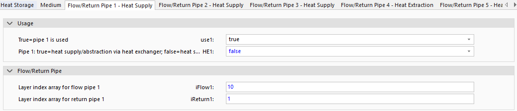
As soon as use1 is activated, the inlet and outlet temperatures of the connections can be set indirectly via iFlow1 and iReturn1. These parameters specify the storage layers in which the connections are attached. The higher the number of these parameters, the higher the connection is attached to the storage tank ( maximum is the number of connections n) and the higher is the temperature of the fluid. The HE1 parameter is dealt with in the Heat Exchanger section.
Environment
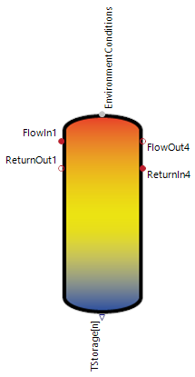
After setting the EnvironmentInput parameter to true, the ▶TEnvironment connector is converted into a environment connector ▶EnvironmentConditions. This change dynamizes the calculation of heat losses to the environment and the storage tank now cools down compared to the outside air temperature.
Heat Exchanger
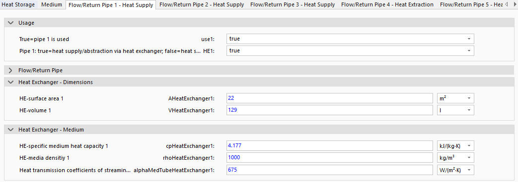
By activating the HE1 parameter, the heat in the connections ▶FlowIn1 and ▶ReturnOut1 is no longer exchanged directly via the heat transfer of the liquid (mixture of liquids within the heat storage), but indirectly via a heat exchanger.
After activation, the heat transfer is determined via the heat transfer surface of the heat exchanger AHeatExchanger, the volume of the heat exchanger VHeatExchanger, the heat transfer coefficient of the medium in a tubular pipe (alphaMedTubeHeatExchanger) and the characteristic thermodynamic values of the medium at operating temperature within the heat exchanger (specific heat capacity cpHeatExchanger and density rhoHeatExchanger). The standard material values entered at correspond to the material values of water.
Model Background
What is the difference between the Heat Supply and Heat Extraction connections?
The storage connections are designed so that for Heat Supply the volume flow enters the storage from the ▶FlowIn (hot) connector and exits via the ▶ReturnOut (cold) connector, thereby introducing heat into the storage. Heat Extraction is designed the other way around. Ensure, these conventions are adhered to avoid numerical instabilities.
Heat Transfer
The heat transfers in the HeatStorage model are calculated for each layer of the storage tank and use the equations from the following figure.
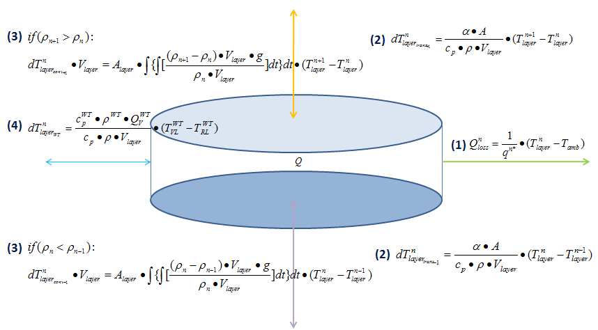
Legend for the heat transfers in the figure:
(1) Heat losses through the insulation
(2) Heat transmission between neighboring heating medium layers
(3) Buoyant force of heating medium due to temperature-dependent density differences - requires the temperature-dependent heating medium density definition (supplied via a table in the input parameters)
(4) Heat extraction via volume flow input - the correspondent volume flow output does not extract heat directly (output volume flow has storage temperature level), but colder heat medium simultaneously flows back into the tank (i.e. heat extraction).
(4) Heat supply or extraction via heat exchangers
The temperature change of the thermal layer of the storage tank results from the heat balance of the above-mentioned heat transfers and is calculated for all thermal layers of the storage tank in each time step.
SOC Definition
The SOC of 100% is defined as the whole storage (every layer) has reached the temperature of the layer with the highest temperature.