SolarController
Symbol | 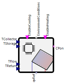 |
|---|
Use
The solar thermal controller model, controls the heat or cooling power output of a solar thermal collector. It ensures that the specified temperature is reached if possible. E.g. this setpoint can be a desired storage tank temperature.
The SolarController covers the following applications:
Basic: In the standard case, the SolarController is used to control the volume flow through a solar collector in such a way that a desired temperature is reached. If the collector is warmer than the storage tank, for example, the storage tank can be heated using the collector. If the collector is colder than the desired temperature, it can also be cooled with the help of the collector and its control via the controller.
Only Heat: In this case, the collector is only used for heating. It is controlled in such a way that no cooling capacity is provided.
Only Cold: In this case, the collector is only used for cooling. It is controlled in such a way that no heating capacity is provided.
Parameters and Connectors
Basic
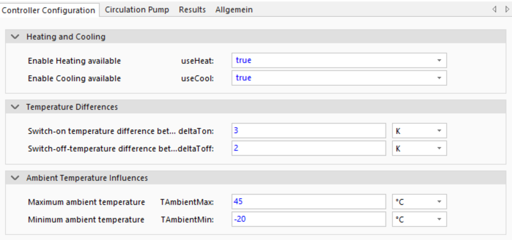
The SolarController provides a Boolean (▶CPon) and a real signal (▶qvRef) to control the circulation pump on the solar collector. These are switched on if heating is required (▶EnableHeating) and the temperature difference (▶TCollector-▶TStorage) is greater than deltaTon or cooling is required (▶EnableCooling) and the temperature difference (▶TCollector-▶TStorage) is less than - deltaTon. It is switched off if the temperature difference is less than deltaToff (heating case) or greater than - deltaToff (cooling case). To avoid numerical difficulties, the switch-off level must be defined slightly below the switch-on level (deltaToff < deltaTon). Only heating ▶EnableHeating or cooling is ▶EnableCooling is allowed, do not set both connectors simultaneously.
To ensure safe system operation, the ambient temperature (provided via ▶EnvironmentConditions) must be within the TAmbientMax and TAmbientMin limits. If the temperature exceeds or falls below these limits, the circulation pump is not given a switch-on signal.
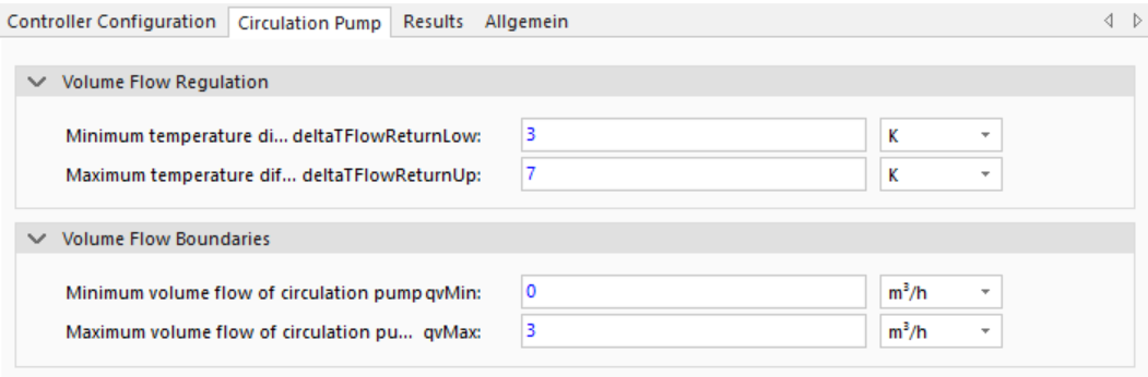
The reference volume flow is regulated when the controller has switched-on. It dependents on the desired temperature range of the heating medium between flow (▶TFlow) and return (▶TReturn) pipe. This difference should be within the limits of deltaTFlowReturnLow and deltaTFlowReturnUp. The volumetric flow is within the limits between qvMin and qvMax.
Only Heat
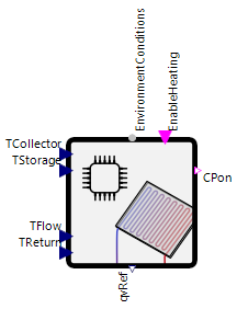
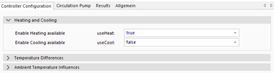
In this case, the collector is only used for heating. Only the switch-on conditions of the heating case from the Basic section are considered. The ambient temperature limits and the calculation of the volume flow remain the same.
Only Cold
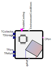
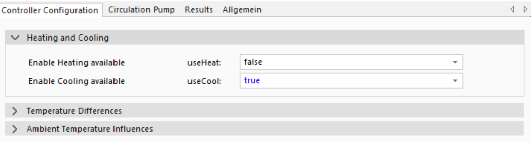
In this case, the collector is only used for cooling. Only the switch-on conditions of the cooling case from the Basic section are considered. The ambient temperature limits and the calculation of the volume flow remain the same.
Model Background
Volume Flow Control
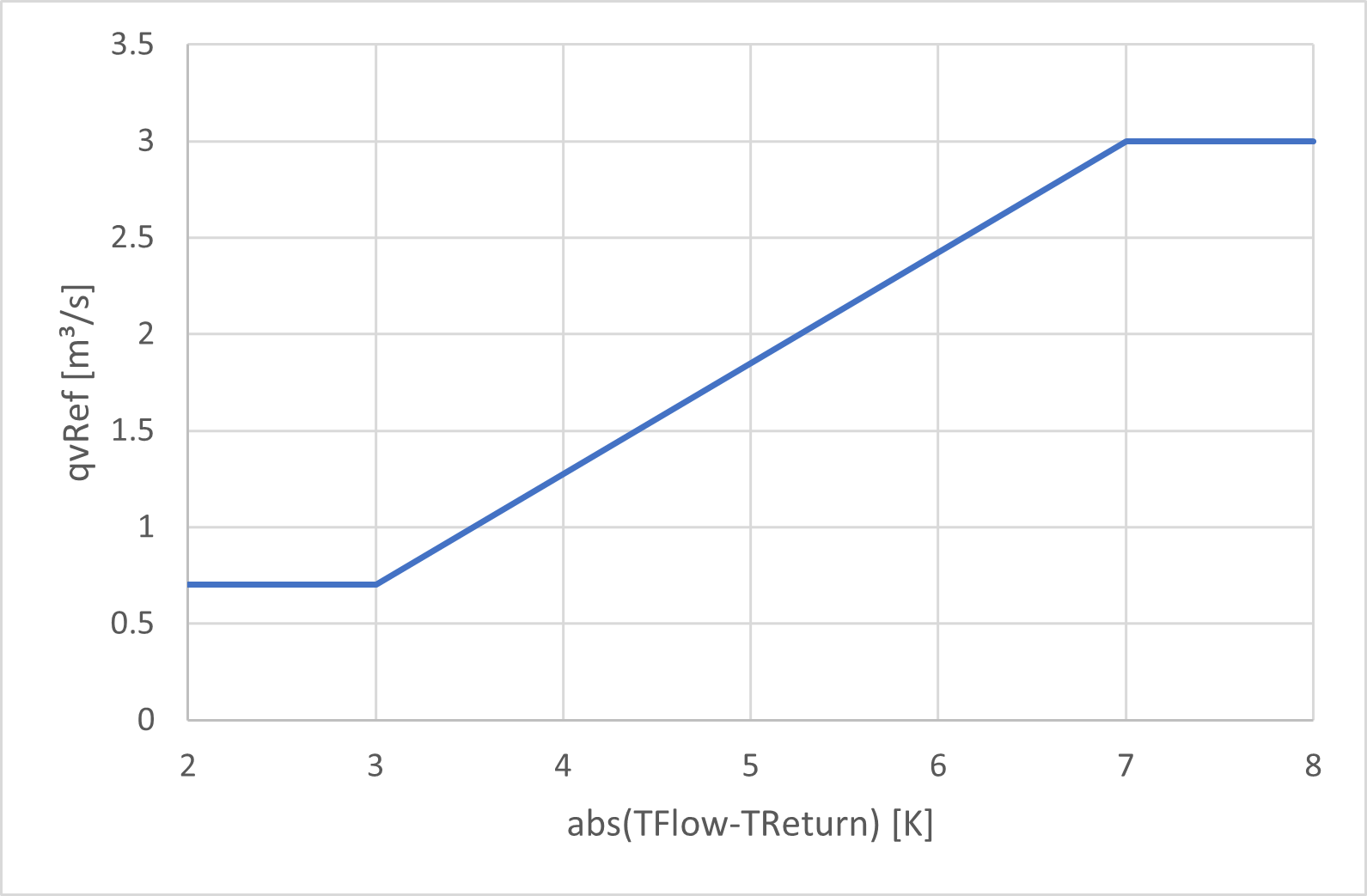
For the calculation of the volume flow the following principles are applied and shown in the image:
If: abs(▶TFlow-▶TReturn) < deltaTFlowReturnLow (in the image 3 K), the reference volume flow is at minimum level (qvMin in the image 0.7 m³/s).
If: abs(▶TFlow-▶TReturn) > deltaTFlowReturnUp (in the image 7 K), the reference volume flow is at maximum level (qvMax in the image 3 m³/s).
Between the two temperature boundaries the reference volume flow is linearly interpolated.
Using the absolute value function ensures that the control functions correctly in heating and cooling mode.