Cable
Symbol | 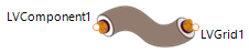 |
|---|
Use
The cable component simulates the internal voltage drop in a cable between an electrical component and the grid.
Parameters and Connectors
To connect the cable to the components, connect the connectors ▶LVComponent1 to the electrical connector of the component and ▶LVGrid1 to the ac grid. Ensure that the port direction is correctly considered.
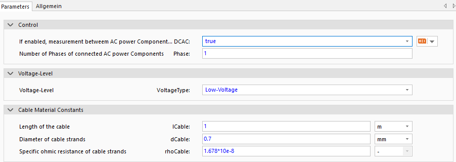
Depending on the current type (ac if DCAC is true, else dc) , the number of phases n (1 - 1 phase AC or 3 - 3 phase AC) and the VoltageType (low voltage, medium voltage, or high voltage) parameters are the connectors configurated. In the example with an 1-phase low-voltage ac grid (DCAC is true, n is 1 and VoltageType is Low-Voltage) the connector ▶LVComponent1 must be connected to the component connector, which should be measured and the connector ▶LVGrid1 to the ac grid. Ensure that the connectors are connected to the correct component.
Also add the cable parameters length lCable, diameter of cable strands dCable and the specific ohmic resistance of the cable strands rhoCable to the component.
Model Background
Voltage Drop Calculation
The following formula is used to calculate the voltage losses within the cable: