Grid
Symbol | 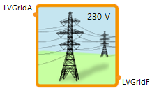 |
|---|
Use
The grid component sums the overall power demand of the connected (maximum of 6) components.
The Grid covers the following applications:
Basic: Normal grid connection for the different components
Sub Grid For Sum Calculation: Activate a new connector to let the current grid (sub grid) connect to a main grid (sum of different grids and components)
Grid For Transformer: Connect the current grid via a transformer to a grid of another voltage level
Parameters and Connectors
Basic
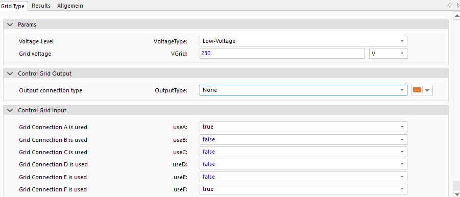
The grid in the basic configuration (OutputType is None) has up to 6 connectors ▶LVGridA to ▶LVGridF, which can be activated using the parameters useA to useF. With the parameter VoltageType sets the voltage level of the grid to differentiate the voltage levels of the grids. Note that the corresponding grid voltage VGrid has to be set individually (value examples are low-voltage: 230 V, medium-voltage: 10 kV and high-voltage: 100 kV).
Furthermore, the RMS-grid voltage VGrid is used to define the current flowing from or to each connected component. Using the resulting phase angle, the grid model calculates the actual effective and reactive power demand of each connected device, per phase and the overall power demand.
If the overall power P is positive the power demand is summed and an electrical energy demand determined ESupply. If negative, the resulting power P is summed and used to define the electrical energy fed into the grid EFeed.
Sub Grid For Sum Calculation
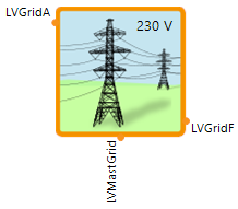

When the parameter OutputType is set to Master Grid the connector ▶LVMasterGrid is visible and allows to connect the current sub grid to another master grid (normal connector ▶LVGridA to ▶LVGridF) that other master grid will then sum up all the individual grid components together.
Grid For Transformer
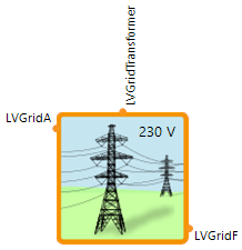

When the parameter OutputType is set to Transformer the connector ▶LVGridTransformer is visible and allows to connect the Grid to another Grid with different VoltageType via a transformer model.