CHPControlHeatLed
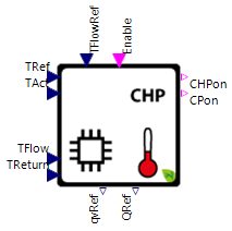
Symbol | 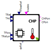 |
|---|
Use
CHPControlHeatLed controls the operation of a simulated combined heat and power unit (CHP) prioritizing the heat demand (i.e. temperature spread between actual and reference temperature) of an external heat sink (e.g. building, heat storage, heat supply via hydraulic shunt).
The CHPControlHeatLed covers the following applications:
Basic: CHPControlHeatLed for a CHP with a constant heating power, no auxiliary heating elements and an ambient temperature independent volume flow control
Ambient Flow Regulation: Control the CHPs volume flow based on the ambient temperature
Heating Power Modulation: Heating power of the CombinedHeatAndPowerUnit can be modulated
Auxiliary Heating: CHPControlHeatLed is enabled to control the CHPs internal electrical heating components through parameterization
Parameters and Connectors
Basic
The CHP controller requires the various temperatures as input parameters to control the CHP:
Setpoint temperature in the flow line on the heat sink side ▶TFlowRef
Setpoint temperature to which the CHP is to be controlled ▶TRef
Current temperature of the component to which ▶TRef is to be controlled ▶TAct
Temperature in the flow line on the heat sink side ▶TFlow
Temperature in the return line on the heat sink side ▶TReturn
The Boolean connector ▶Enable, which comes from an external controller or input signal and specifies when the CHP should be active, must also be connected. ▶Enable allows the implementation of a complex switch-on control for the CHP in addition to the internal control of the CHP controller and to control the CHP autonomously the connector can be defined with a static true argument. To control the reference temperature independent of the ambient temperature define an own temperature target curve with ▶TFlowRef. The output parameters must then be linked to the respective input parameters of the CHP model.
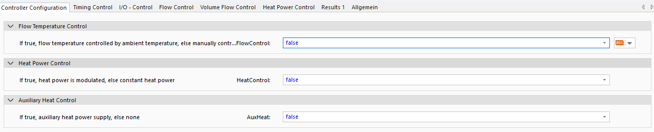
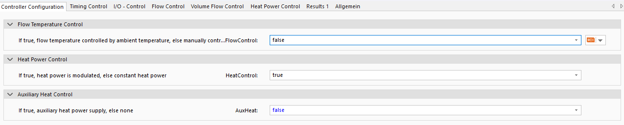
The CHPControlHeatLed is parameterized to control the model independent of the ambient temperature (FlowControl is false), to have a constant heating power without CHP modulation (HeatControl is false) and to not have any auxiliary heating system (AuxHeat is false).

The user is given the possibility to vary internal operation time constants (e.g. minimum switch-on/off time etc.) of the CHP controller. These times are the delay in starting the CHP compared to the circulation pump tDelayCHP, the minimum switch-on time tCHPminOn and the minimum switch-off time of the CHP tCHPminOff. If the corresponding data files of CHP controller are not available the pre-defined values should be used. For the circulation pump, there is also a time delay for switching off the circulation pump compared to the CHP tDelayCP. More information is available in the Model Background.

When the maximum flow temperature TFlowMax or maximum return temperature TReturnMax is reached, the CHP is switched off by the controller. While the parameters deltaTActRefLow and deltaTActRefUp represent the limit values for switching the CHP on or off.

The flow temperature of the CHP is controlled by a temperature hysteresis using the max difference between the flow temperature ▶TFlow and the reference flow temperature ▶TFlowRef (in the current flow control mode FlowControl). For the parameterization of deltaTFlowRefMax and deltaTFlowRefMin use the help of the background information.
The maximum volume qvMax depends on the selected circulation pump (ref. GreenCity/Data/ModelData/CHP/circulation_pump), however the minimum volume flow qvMin can be defined using the CHP system data sheet. Ensure that the minimum volume flow qvMin is set to a value above zero, otherwise the volume flow control is not activated. Note that the minimum volume flow should be set to a level where heat power output is possible with an adequate temperature spread (▶TFlow-▶TReturn). If this value is too high, the volume flow control can cause system state faults. More information is available in the Model Background.
Ambient Flow Regulation
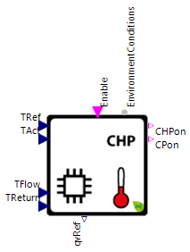

Setting the parameter FlowControl to true, the reference flow temperature of the CHP is defined dependent on the ambient temperature over the connector ▶EnvironmentConditions and used to control the reference volume flow of the CHP.
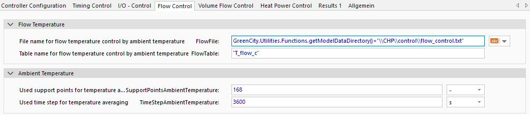
The reference flow temperature is defined using the flow temperature characteristics specified in the model data directory FlowFile (GreenCity/Data/ModelData/CHP/control which is not visible in SimulationX) and the decision for a table FlowTable, which maps the ambient temperature to a target flow temperature. If the prepared flow temperature curves doesn't match the desired curve, use the FlowFile as template for your own target flow temperature curves.
To avoid high dynamic oscillations during the simulation the average ambient temperature is used for flow temperature control. To calculate the average ambient temperature a number of support points SupportPointsAmbientTemperature and a time step size TimeStepAmbientTemperature must be defined in the flow control parameter dialog. The time difference between each data point characterizes the time step TimeStepAmbientTemperature. Note that for the calculation the initial ambient temperature is used as a data point for every support point. If a static reference flow temperature is to be used for the simulation, the FlowControl parameter under Controller Configuration should be set to false.
Heating Power Modulation
At the activation of the heating power modulation (HeatControl is true) the output connector ▶QRef is visible and must be connected to the CHP.

To control the upper and the lower limit of the heating power QHeatMax and QHeatMin use the information from the CHP data sheet.
Auxiliary Heating
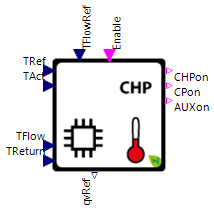

At the activation of the auxiliary heating system (AuxHeat is true) the output connector ▶AUXon is visible and must be connected to the CHP.

To ensure that the auxiliary heating system is only switched-on when the heat demand of the consumers can not be supplied by the CHP, it only is activated if the actual heating system temperature is below the minimum level, for a pre-defined time period (tBivalence).

In the tab I/O - Control the switch on and switch off temperature differences (deltaTAuxRefLow and deltaTAuxRefUp) must be defined. The switch-off temperature level of the auxiliary heating system deltaTAuxRefUp should be set below the correspondent temperature level, for the overall system switch-off deltaTActRefUp, to avoid extensive usage of the auxiliary heating system (i.e. the auxiliary heating system should work as a slave system only when needed). More information is available in the Model Background.
Examples
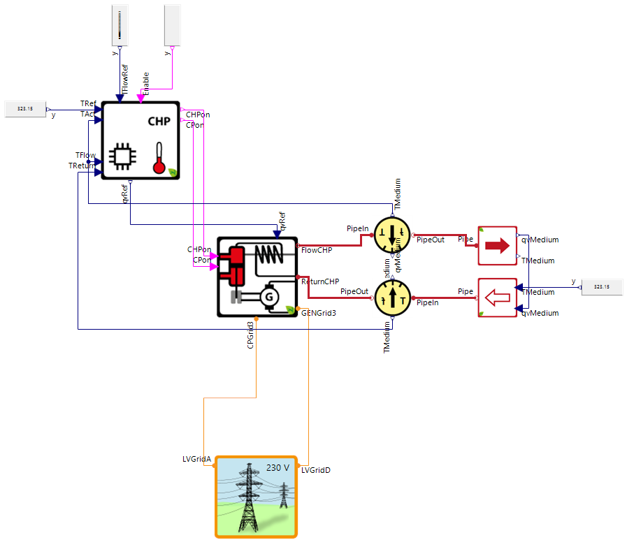
The image above shows a highly simplified example of the use of the CHPControlHeatLed, which is intended to demonstrate the connection of the components via the connectors. The example shows the integration of a controlled CombinedHeatAndPowerUnit into a heat sink (e.g. a house heating system) assuming a constant return temperature.
Model Background
Pre- and Post-run Time of Components
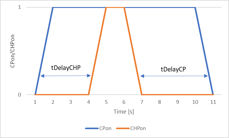
The logic of the time delay can be seen in the following figure. The CHP (▶CHPon) is only switched on after the circulation pump is switched on and the time tDelayCHP (3 seconds in the figure) has elapsed. The logic for tDelayCP is analogue. This results in the ▶CHPon signal being switched on at 4 s after the circulation pump is switched on at time step 1 s. The circulation pump is then switched off 4 s (tDelayCP) after the unit is switched off.
Prevention of Continuous Switching
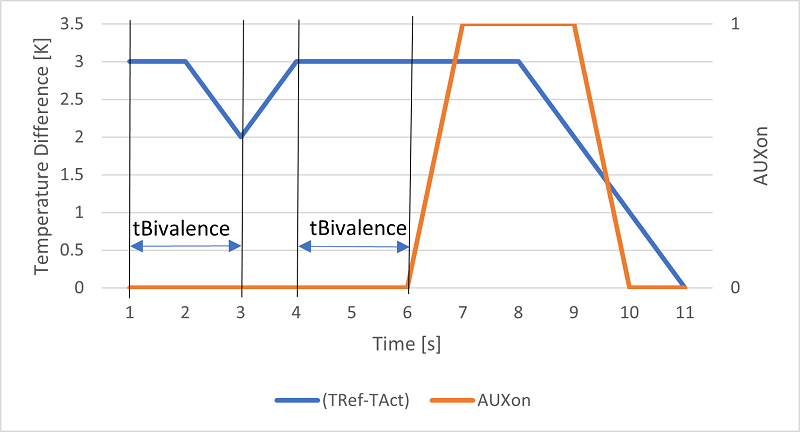
The following illustration shows how the tBivalence parameter works. In this case, it is assumed that the switch-on limit (deltaTAuxRefLow) for the auxiliary heating is 3 Kelvin and the switch-off limit (deltaTAuxRefUp) is 1 Kelvin. This temperature difference is calculated by TRef-TAct. The image shows that the switch-on limit must be reached for at least the duration tBivalence (here 2 seconds) . If the temperature difference decreases within this period (as in the first case at time 3 s), no switch-on signal is issued. The auxiliary heating is only switched on when the temperature difference is reached for a full 2 seconds period (in the image at time 6 s). ▶AUXon is then switched off when the temperature falls below the lower temperature limit at time 10 s.
Volume Flow And Heating Power Modulation Control
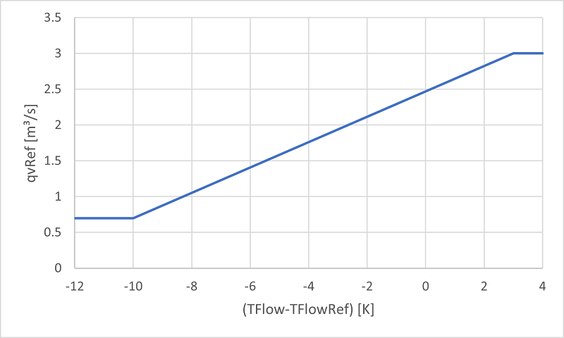
The volume flow of the circulation pump is defined by a linear approach as shown in the following figure. The decisive factor is the temperature difference between ▶TFlow and ▶TFlowRef. At the value deltaTFlowRefMax (in the image 3 K) the maximum volume flow qvMax is assumed to reduce the temperature stroke inside the generator. At the temperature difference deltaTFlowRefMin (in the image -10 K) the minimum volume flow qvMin is used to limit the temperature stroke. Linear interpolation takes place between the extreme values in order to achieve the desired set flow temperature ▶TFlowRef.
If the heating power is modulated, it's behavior is analogue to the volume flow control.
Switch on/off
The CHP heat led controller uses the maximum flow and return temperature and a temperature hysteresis around the reference temperature of the connected heating system (heat storage, hydraulic shunt, building zone) as a control parameter to switch the system on/off:
If an auxiliary heating system is to be controlled a corresponding temperature hysteresis using the reference temperature of the connected heating system must be defined: