CombinedHeatAndPowerUnit
Symbol | 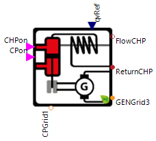 |
|---|
Use
Combined heat and power units (CHPs) are modular devices for heat and electricity production. They can be controlled using external controllers prioritizing either heat or electricity production. CHPs produce electricity with an internal combustion engine that drives a generator. In this process, excess thermal energy is used for heating. This way the efficiency of heat and electricity production can be increased. Bio-gas, natural gas, diesel or benzine are most commonly used as fuel (parameterization of fuel type in the model is done via volumetric and energy density of the fuel).
The CombinedHeatAndPowerUnit covers the following applications:
Basic: CombinedHeatAndPowerUnit with constant heating power output and and 1-phase circulation pump connection (dc)
Heating Power Modulation: Heating power of the CombinedHeatAndPowerUnit can be modulated
Auxiliary Heating: CombinedHeatAndPowerUnit is enabled to use internal electrical heating components through parameterization
3 Phase Electrical Connection: In the current setup the CHP is connected to a 3-phase main supply (ac)
Parameters and Connectors
Basic
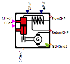
In the basic configuration the model has to be connected using the turn on/off signals for the CHP and the circulation pump (▶CHPon and ▶CPon), set point of the volume flow ▶qvRef, the intake and return pipes of the heat sink side (▶FlowCHP and ▶ReturnCHP), the ac grid connection for the CHP power generation (▶GENGrid3) and the dc grid connection for the circulation pump consumption (▶CPGrid1). Most of the connectors should be set with either the heat regulated or the current regulated controller for the CHP.
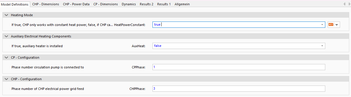
The CombinedHeatAndPowerUnit is in the basic configuration adjusted for a constant power output (power is on or off with HeatPowerConstant is true), no auxiliary heating system (Auxheat is false), 1-phase circulation pump connection ( dc, CPPhase = 1) and 3-phase CHP grid connection (ac, CHPPhase = 3).
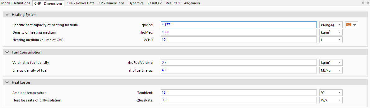
The material values of the medium in the heating system (specific heat capacity cpMed, density rhoMed and the volume of the heating medium in the CHP VCHP) are used to calculate the heat transfers. The volumetric and energetic density of the fuel (rhoFuelVolume and rhoFuelEnergy) is used to calculate the fuel consumption and the Heat Losses are the last group of parameters required to calculate the heat transfer on the heat sink side of the CHP. The parameters ambient temperature TAmbient and the heat loss rate of the insulation QLossRate are used for this.
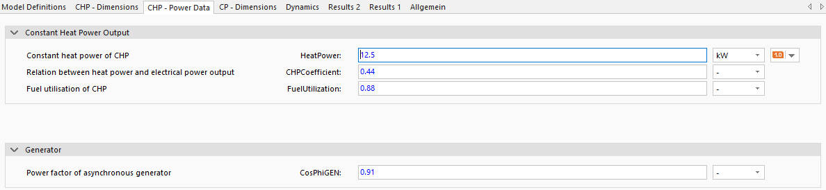
The electrical power of the circulation pump is calculated using a predefined file with the pump power as a function of the volume flow CPFile (not visible in SimulationX). So that this file can be read in meaningfully, the name of the table within this file CPTable must be specified and the power from the table is calculated with the power factor of the pump CosPhiCP. For a faster and more accurate simulation of the pump parameters, the maximum and minimum pump volume flows in the piping system qvMax and qvMin must be defined.the CHP - Power Data tab defines the constant heat output of the CHP in operation HeatPower, the ratio of heat output and electrical output CHPCoefficient and the fuel utilization rate FuelUtilization. The power factor CosPhiGEN is also defined for the generator. If no values are known for CHPCoefficient, FuelUtilization and CosPhiGEN, then the default values entered can be assumed.
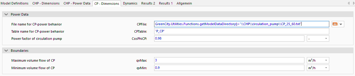
The electrical power of the circulation pump is calculated using a predefined file with the pump power as a function of the volume flow CPFile (not visible in SimulationX). So that this file can be read in meaningfully, the name of the table within this file CPTable must be specified and the power from the table is calculated with the power factor of the pump CosPhiCP. For a faster and more accurate simulation of the pump characteristics, the maximum and minimum pump volume flows in the pipe system qvMax and qvMin must be defined.
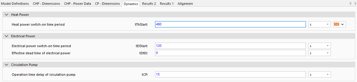
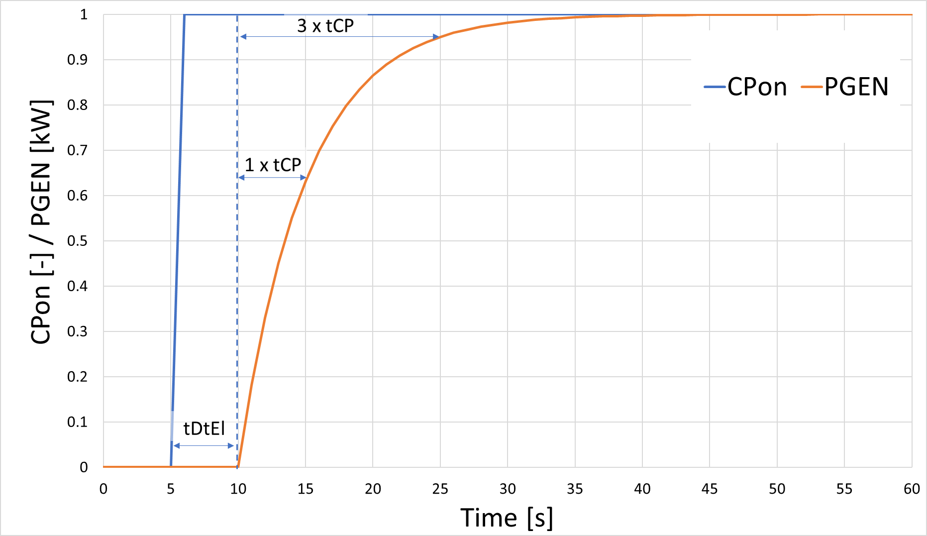
To simulate the behavior of the CombinedHeatAndPowerUnit, the model uses the typical start-up times during the start process for the heat power of the CHP tThStart and the electrical power of the CHP TElStart and the dead time (time delay between change in input signal and reaction) of the electrical power tDtEl. The run-on times for the circulation pump tCP defines how much time the circulation pump is on before the starting of the CHP or after the shut-down of the CHP. For more information see time dynamics.
Heating Power Modulation


For modulated CHPs (HeatPowerConstant is false) the max and min modulated heat power HeatPowerMax and HeatPowerMin must be defined and the associated CHP data file supplied CHPFile (i.e. specifying temporal based CHP coefficient CHPTable and fuel utilization FuelTable). If other CHP systems are to be modeled the CHP data file in the model data directory (not visible in SimulationX) can be used as a template. To define the set point of the heat power the connector ▶QRef has to be connected to a defined value of the heating power.
Auxiliary Heating
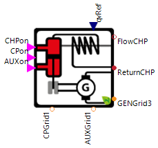

The parameter AUXheat allows for the modeling of an auxiliary, internal, electric heating system of the CHP. Such a system increases the heat power output when the heat demand exceeds the maximum heat power output of the CHP system. To model to auxiliary heating system in more detail define, if the heating system is a 1-phase (dc) or 3-phase (ac) system with the parameter AUXPhase and connect ▶AUXGrid1 with to corresponding dc grid or ac grid.

This model functionality must be configured by defining the electrically produced heat power output of the auxiliary system AuxHeatPower.

Also, the time delay for the auxiliary heating system control of the PT1 element tAUX has to be defined under Dynamics.
3 Phase Electrical Connection
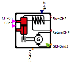

If the individual components of the heat pump have an ac connection, the number of phases for the individual components (CPPhase, and CHPPhase) can be changed to 3, i.e. ac, in the Model Definitions tab which also shows the new connector ▶CPGrid3. This is important to assess if these systems cause unsymmetrical electric loads within the grid.
Examples
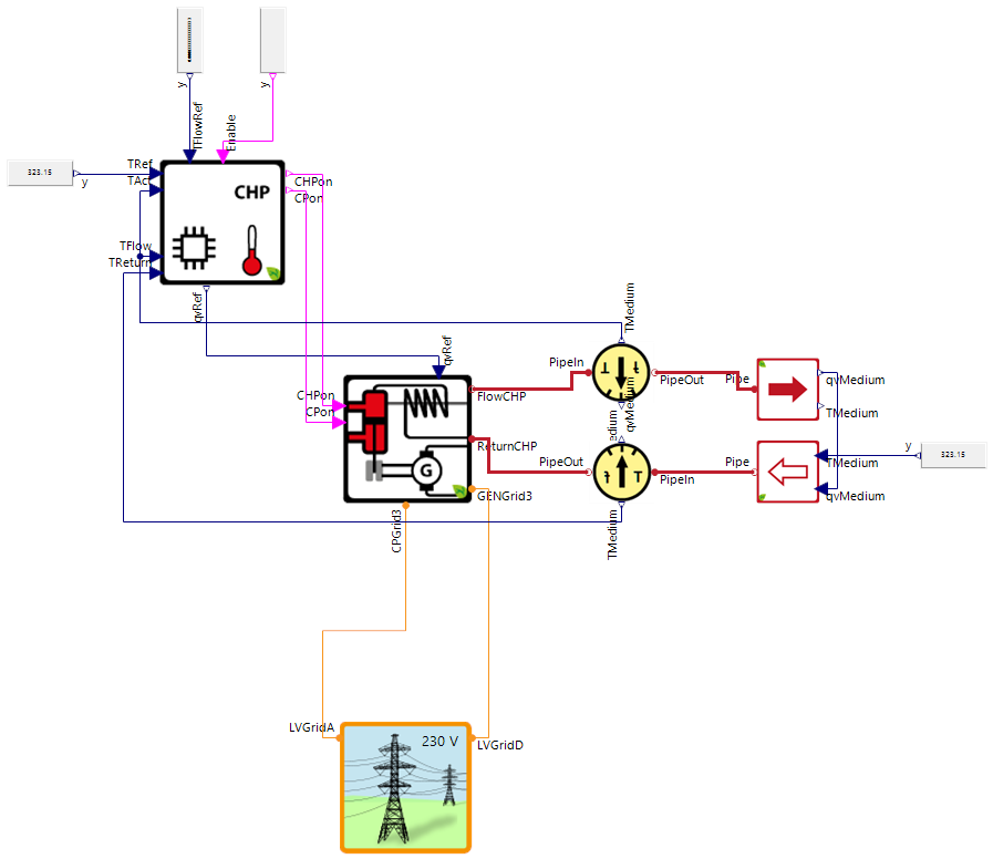
The image above shows a highly simplified example of the use of the CombinedHeatAndPowerUnit, which is intended to demonstrate the connection of the components via the connectors. The example shows the integration of the controlled CombinedHeatAndPowerUnit into a heat sink (e.g. a house heating system) assuming a constant return temperature.
Model Background
Time Dynamics
The times of the pumps and the CombinedHeatAndPowerUnit are modeled in the model via PT1 elements, whereby the entered parameters (e.g. tThStart and tCP) represent the time constant of the PT1 element and the dead time tDtEl is the time without any reaction of the model to changes in the controls. When the CombinedHeatAndPowerUnit is switched on, the electrical and thermal powers (e.g. PCP, PGEN, QHeat and PAux) increase according to the typical behavior of the step response of a PT1 element. This means that after once the time constant (e.g. tCP = 5s) the electrical and heating power rise to 63% of its original value, after twice the time constant (2 * tCP) to a value of 95% and after five times the time constant (5 * tCP) to 99.2%.