HeatingCoolingLoad
Symbol | 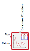 |
|---|
Use
This component can be used to integrate thermal loads, represented by existing power time series, into a model. The time series can be read from a text file and imported into the simulation.
Parameters and Connectors
Basic
For the load data import the path to the text file must be specified by the parameter File and the table name (name of the values column within the text file) by the parameter Table. The table values are interpreted in [W] (SI-Unit). The file dependent curve can be interpreted as a heating or cooling load. This is specified by the parameter useHeat. Both heating and cooling power characteristics must be positive in the associated text file.
The timebase of the load table can either be supplied in hours of year (useDayTime=false) or in hours of a day (useDayTime=true). Using the latter format, simulations longer than a day will repeat the given load curve accordingly.
Based on the power time series the required volume flow (i.e. to cover the demand load) of a heating or cooling medium is calculated using the following equation:
To solve this equation a return temperature is required. Thus a reference temperature is set with parameter TRefReturn as an absolute value. To limit the volume flow upwards, either activate the Boolean parameter useMaxVolFlow and specify a fixed maximum volume flow by qvMax, or set a minimum temperature difference deltaTMin with useMaxVolFlow deactivated.
Furthermore, in the heating case, the model can add simple heat pump functionality between consumption and supply. To do this, set the withHeatPump parameter on the Heat Pump Properties tab to true. This allows you to assign a COP to the heat pump (COPHP), which is then used to calculate the required electrical power and the source power. Instead of the full heating power required, only the source power is then drawn from the connected heat supply.
The nPhase parameter can be used to apply the electrical power to a single-phase connection or distribute it evenly across 3 phases.
As the model imitates an electrical device, the power factor must be considered which is the ratio between the real power to the apparent power and can be defined using power factor parameter cosPhiHP.
The Connector ▶EnvironmentConditions has to be connected to an Environment block to provide the current time of year and time of day for reading the text file. The ▶Flow and ▶Return connectors should be connected to a heating or cooling supply (ideally indirectly via a storage tank). The connected heating or cooling supply should define the flow temperature. The volume flow and return temperature are calculated by the HeatingCoolingLoad.
Model Background
From the parameterised text file, the value corresponding to the current timestamp is read into the model. The values are interpreted as heating or cooling power in watts. Linear interpolation is applied between the individual table points, and extrapolation is performed outside the given time series.
The volume flow qv is calculated using formula (1) based on the given heating or cooling capacity. The calculation of the return temperature referenced here is switched depending on whether it is a heating or cooling load and whether the volume flow is limited by qvMax or deltaTMin.
useHeat=true:
useMaxVolFlow=true:
useMaxVolFlow=false:
useHeat=false:
useMaxVolFlow=true:
useMaxVolFlow=false: