HybridCoolingTower
Symbol | 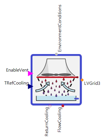 |
|---|
Use
A hybrid cooling tower can cool a medium with the help of outside air. The medium remains in a closed circuit. To increase the heat transfer to the surrounding air a ventilator is used to increase the air volume over the heat exchanger. This raises the heat transfer coefficient of the system. In addition, the heat exchanger can be wetted with water to achieve an additional cooling effect via evaporation.
Parameters and Connectors
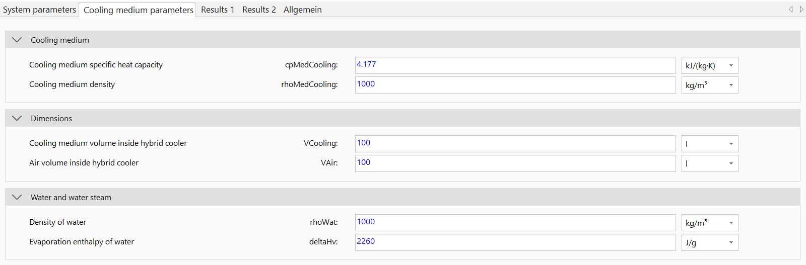
The cooling medium (defined by cpMedCooling and rhoMedCooling) is transferred to the cooling tower via the ▶FlowCooling and ▶ReturnCooling pipes. The target temperature that the cooling medium should reach in the cooling tower can be transferred via the ▶TRefCooling connection. ▶EnvironmentConditions must also be connected to define the outside air temperature.
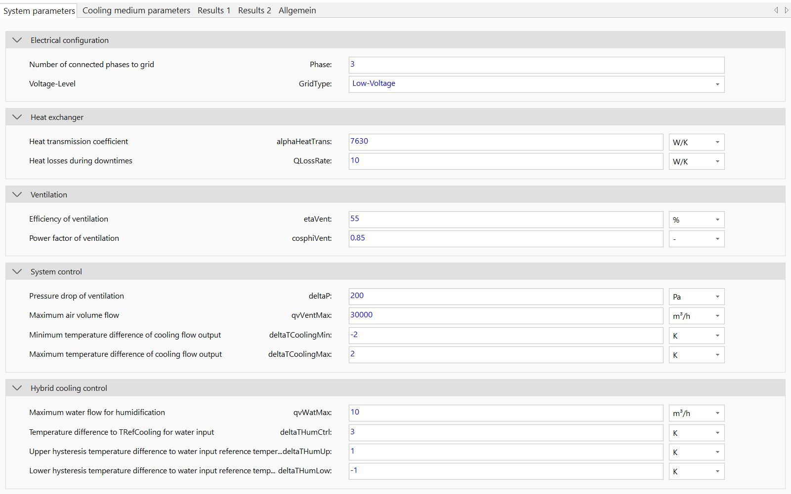
The parameter dialog can be used to characterize the dry cooling tower model. To adapt the cooling tower to higher cooling power (i.e. imitation of higher heat exchanger surfaces) only the heat transmission coefficient alphaHeatTrans needs to be modified. Parameters such as the heat transfer rate during downtimes (QLossRate) and the volumes of the cooling medium (VCooling) and the air (VAir) can be used to validate and fine-tune the model.
Input ▶EnableVent can be used to enable the fan. With the parameters of the pressure drop (deltaP), efficiency (etaVent) and power factor (cosphiVent) the power requirement (▶LVGrid3) of the fan can be calculated. Different connections like one- or three-phase (Phase) and voltage levels (GridType) are possible.
If ventilation is enabled, the air volume flow (qvVent) is determined based on the ▶TRefCooling and the current TReturnCooling of the cooling medium and the maximum air volume flow (qvVentMax). The system settings deltaTCoolingMin and deltaTCoolingMax have to be set as well.
The heat exchanger can be wetted with water to reduce the energy requirement of the fan or to increase the cooling capacity. To do this, the density (rhoWat) and enthalpy of vaporisation (deltaHv) of the water and the maximum volume flow (qvWatMax) that can be used must be parameterised. The volume flow of the water is regulated to the ▶TRefCooling with an offset (deltaTHumCtrl) within the limits deltaTHumUp and deltaTHumLow.
Model Background
Calculation Power Demand
The power requirement is calculated linearly using the constant pressure drop (deltaP) as follows:
Calculation Air Volume Flow
The air volume flow is determined linearly based on the difference between ▶TRefCooling and TReturnCooling as well as the permissible deviations deltaTCoolingMin and deltaTCoolingMax.