HydraulicValveReturn
Symbol | 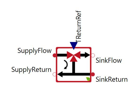 |
|---|
Use
This 3-way hydraulic valve controls the return temperature of a heat supply dependent on heat sink return and heat supply flow temperature. In contrast, the HydraulicValveFlow regulates the flow temperature on the sink side.
Parameters and Connectors
The component ensures the desired return temperature on the supply side by mixing the supply flow (▶SupplyFlow) to the return flow (▶SupplyReturn) on the supply side (see ModelBackground). The desired temperature is specified via ▶TReturnRef. It is important to note that this valve defines the volume flow on the sink side! It must therefore be ensured that the volume flow from ▶SinkFlow corresponds to the incoming volume flow at ▶SinkReturn.
The reference temperature is only reached if this is physically possible. For example, if the temperature at ▶SupplyFlow is lower or the temperature at ▶SinkReturn is higher than ▶TReturnRef the return temperature of the supply will not match the reference temperature.
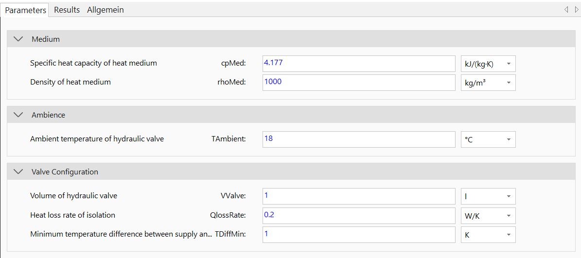
The valve itself can be described in terms of its volume (VValve), the properties of the medium (cpMed, rhoMed) and heat losses (QlossRate, TAmbient). To ensure the numerical stability of the model, a minimum temperature difference (TDiffMin) must be maintained between the flow temperature on the supply side and the return temperature on the sink side.
Model Background
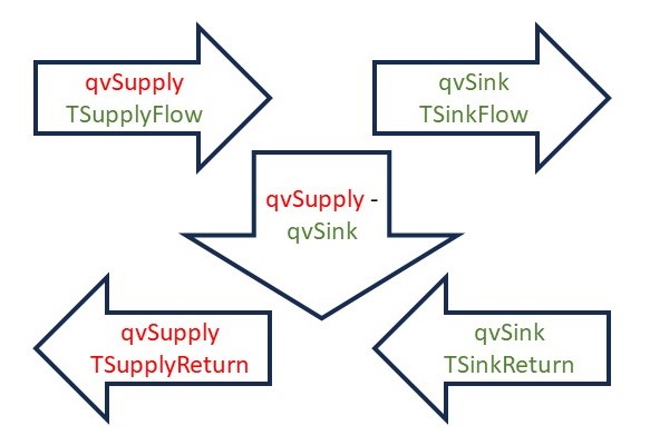
The principle of the component is shown in the following figure. All variables in green are defined outside the component. All variables in red are defined by this component. The goal here is to control the ▶TSupplyReturn to the target ▶TReturnRef. qvSupply acts as a control variable here.