IceStorage
Symbol | 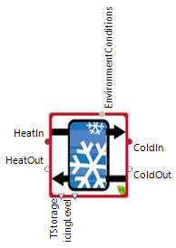 |
|---|
Use
The IceStorage is a special latent heat storage (PCM storage) and is typically used as heat source for heat pumps with low source temperatures between roughly -12 and 20 °C. Heat is extracted from the water causing it to freeze along the heat exchanger tubes or plates. The icing level (the percentage of frozen medium inside the storage tank) thus increases up to 100% if the heat exchanger has sufficient, low temperatures. The internal equations characterize the heat transmission from the liquid storage content through the frozen ice content and the heat exchanger tube. For the heat transfer it is by default assumed that the IceStorage is embedded in the ground without any insulation.
In typical use-cases the storage is cooled in winter by heat pumps and the stored cooling energy (i.e. in the ice) used in cooling systems during the warmer summer (e.g. building cooling). Another possible use case is the peak shaving of cooling demands with the stored energy inside the IceStorage.
The IceStorage covers the following applications:
Basic: The IceStorage can be charged or discharged with a fluid via the heat exchangers. The refrigerant can be freely defined by a record and can be newly implemented. For the heat transfers to the environment or through the heat exchanger to the fluid different heat transfer coefficients can be adjusted.
Parameters and Connectors
Basic
The IceStorage model is considered to be embedded in the floor and requires a connection to the connection with the Environment model via ▶EnvironmentConditions to calculate the heat transfer. For only loading/cooling of the IceStorage, the connections ▶ColdIn and ▶ColdOut are used and for only discharging/heating the IceStorage, the connections ▶HeatIn and ▶HeatOut must be connected. If a heat exchanger is to be used for charging and discharging, then the connections ▶ColdIn and ▶ColdOut must be connected and ▶HeatIn and ▶HeatOut can be left unconnected (More information to thermal connectors).

To calculate the heat transfers within the heat exchangers, the medium within the charging heat exchanger (HeatMedium) and the medium within the discharging heat exchanger (ColdMedium) are required (see figure above). The preset refrigerant Pekasol L 33% is a propylene glycol mixture that has a volume fraction of 33% of propylene glycol in the refrigerant and the remaining proportion is filled with water. This refrigerant is therefore a typical refrigerant for the combined use of heat pumps and ice storage tanks.
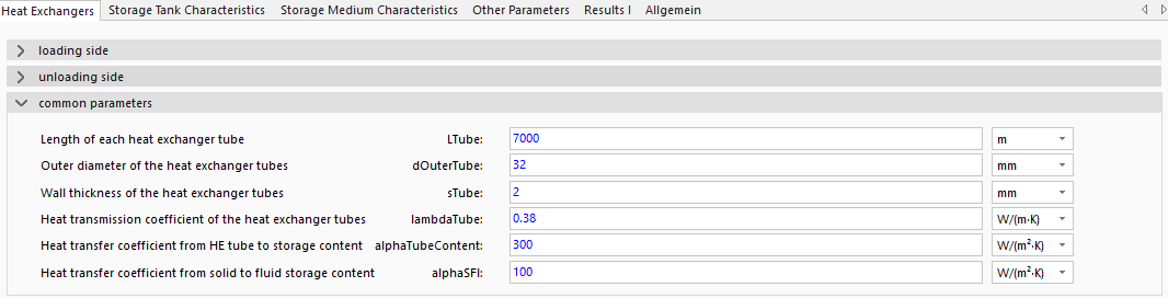
To define the size of the heat exchangers for heat transfer, the geometric parameters heat exchanger length LTube, outer diameter of the tubes dOuterTube, and tube thickness sTube must be specified. If these parameters are not known, the parameter LTube can be adjusted until the maximum heat transfer of the model matches the maximum heat transfer in reality.
To calculate the heat transfer at the heat exchangers, the parameters thermal conductivity of the tube lambdaTube, heat transfer from the tube to the ice storage content alphaTubeContent, and heat transfer from the solid to the liquid ice storage medium alphaSFl must also be specified. If the exact parameters of the storage system are not known, simulations can be performed using the preset values.
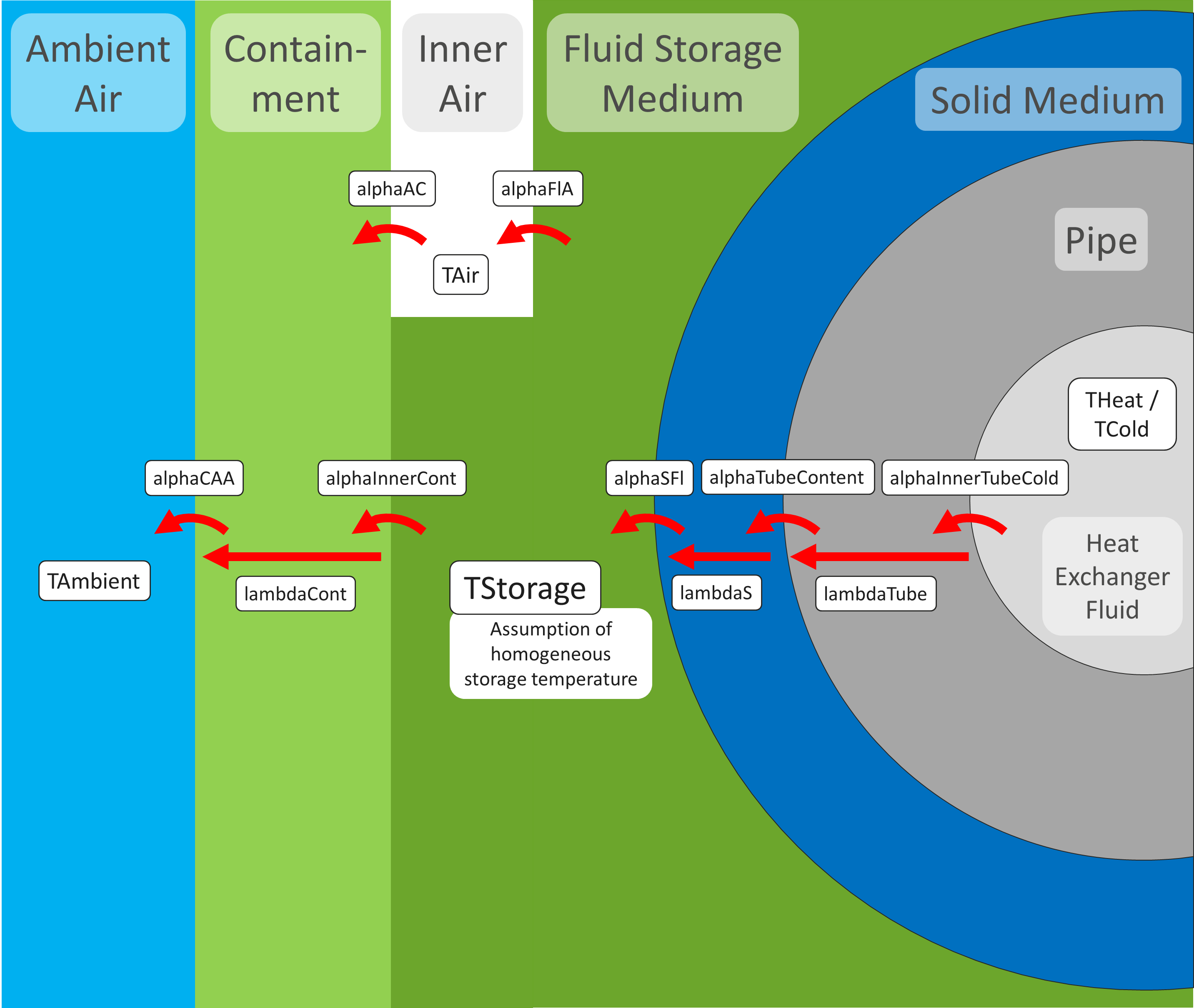
For more information on the thermodynamic factors see the detailed figure with all heat transmission coefficients.
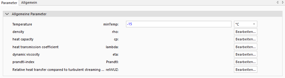
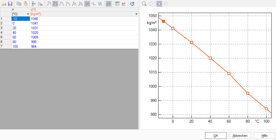
To create your own refrigerant, a record must be created within the StorageSystems/StorageData/FluidMedia/Refrigerants folder analogous to Pekasol L 33% and supplemented with the desired substance data. Most of the substance data can be taken directly from literature. Only the relative heat transfer in relation to turbulent flowing water at +20°C (relWUZ) is not a material value of the fluid, but an experimentally determined quantity. The values of relWUZ are used instead of calculating the heat transfer coefficient from the Nusselt number because the ice store model can this way be adapted to the existing technical and geometric conditions of the respective ice store and the simulation time is significantly shortened. If no values for the relative heat transfer (relWUZ) are known, then the values from Pekasol L 33% can be used.
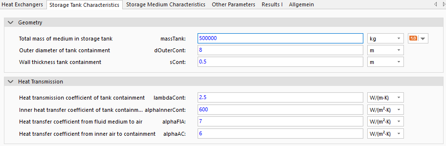
The technical specifications of the IceStorage must be entered under the Storage Tank Characteristics tab and a distinction must be made between the geometric and thermodynamic parameters. The geometric parameters (Geometry) refer to the mass of the medium inside the ice storage tank (massTank), the outer diameter of the storage tank (dOuterCont) and the thickness of the outer wall of the storage tank (sCont). For more information on the thermodynamic factors see the detailed figure with all heat transmission coefficients. The current thermodynamic coefficients are parameterized for an uninsulated storage tank embedded in the floor. To setting an insulated storage tank, the insulation coefficients (lambdaCont, alphaInnerCont, alphaFlA and alphaAC) must be adjusted to a lower value (e.g. 0.2 to 1
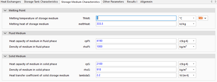
To set the behavior of the fluid within the IceStorage, use the parameters under the Storage Medium Characteristics tab. For the calculations, the parameters of the storage medium melting point (TMelt), heat of fusion (meltHeat), heat capacity and density of the liquid phase (cpFl and rhoFl) and the heat capacity, density and heat transfer coefficient of the solid phase (cpS, rhoS and lambdaS) must be specified. The heat transfer coefficient of the solid phase is required because the solid phase around the heat exchangers acts as insulator. All parameters in the picture above are pre-parameterized with the properties of water.
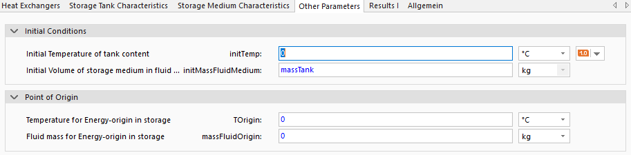
To set the initial state of the IceStorage, the parameters initial temperature (initTemp) and the initial volume or mass of the liquid phase of the storage contents (initMassFluidMedium) must be adjusted. The initial values should correspond to the values at the end of the simulation in order to achieve comparability between different model variants and to eliminate the dependence of the results on the initial conditions. Similarly, the comparability of the simulation results with other measured values is ensured via the setting options for the reference values for the energy calculation (temperature TOrigin and fluid mass massFluidOrigin).
Model Background
Initial Values Implementation
The initial values have some safety measures to correct physically impossible states. These safety measures can lead to deviating behavior between the user input and the actual initial values. The initial temperature initTemp is used as the main criterion for initialization and corrects the specification of initMassFluidMedium. The calculation is realized using the following equation.
Thermal Connectors
The thermal connectors for discharging the ice store ▶HeatIn and ▶HeatOut never have an ice shell/solid phase around the heat exchangers by definition, because these heat exchangers are not used to cool the IceStorage below the melting temperature TMelt. For this reason, the insulating effect of the solid phase does not apply at these connectors and this connector should not be used for a combination of charging and discharging the ice store. For the connectors ▶ColdIn and ▶ColdOut the ice layer thickness is calculated using the volume of the solid phase of the storage medium (see more information to ice thicknes).
Ice Thickness Calculation
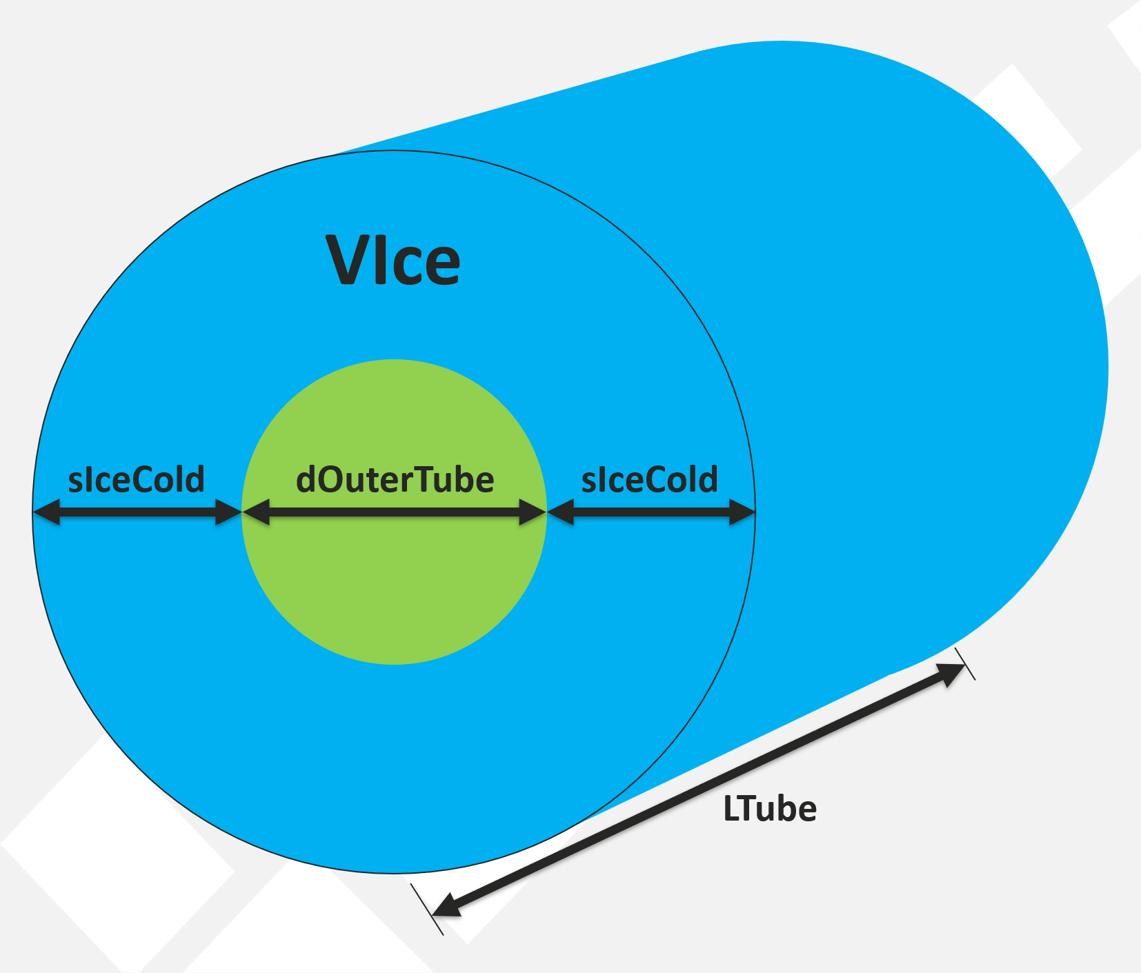
Due to the strong influence of the solid phase as an insulator, the calculation of the ice thickness around the heat exchanger tubes is important for determining the heat exchange between the ice storage tank and the environment. To calculate the ice thickness, it is assumed that the ice accumulates around the heat exchanger tubes in the form of a hollow cylinder (see figure).
Degree Of Icing
The degree of icing of 100% in the model means that the entire storage medium within the storage tank is in a solid phase. This definition differs from the icing degree of most ice storage manufacturers, as they define 100% icing degree as the technically maximum possible conversion volume of the storage medium. Typically, a manufacturer's degree of icing of 100% correlates with approx. 50-60% degree of icing in the model. The differences exist because the exact technical specifications of the different ice storage manufacturers cannot be taken into account in a general model.
Heat transmission coefficient calculation
To calculate the heat transfer coefficient and thus the temperature change/phase change in the storage tank temperature TStorage and in the heat exchanger, the heat transfer coefficients from the following figure are taken into account.