SimpleElectricStorage
Symbol |  |
|---|
Use
The model SimpleElectricStorage is a abstract model of a non-specific, electric energy storage and can be used for electrical storages where the specific technical data is not known. As the model is not specific it can be used for all types of electrical storages like batteries, redox-flow batteries, flywheels, supercapacitors or other applications.
The SimpleElectricStorage covers the following applications:
Basic: The SimpleElectricStorage is parametrized with basic storage behavior like charging and discharging curves, capacity and maximum charging and discharging power. The model additionally, considers different efficiencies for charging and discharging.
1-Phase Grid Connection: The grid connection is changed to a 1-phase low voltage grid connection.
Parameters and Connectors
Basic
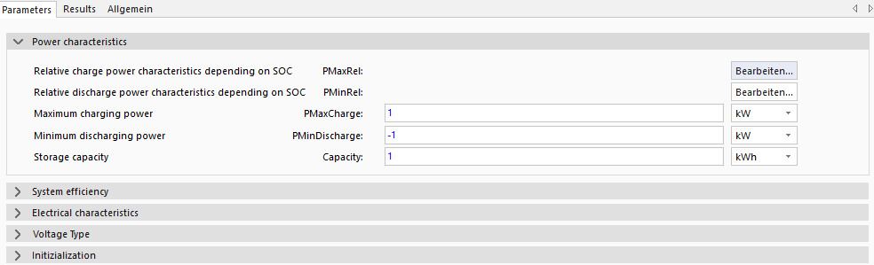
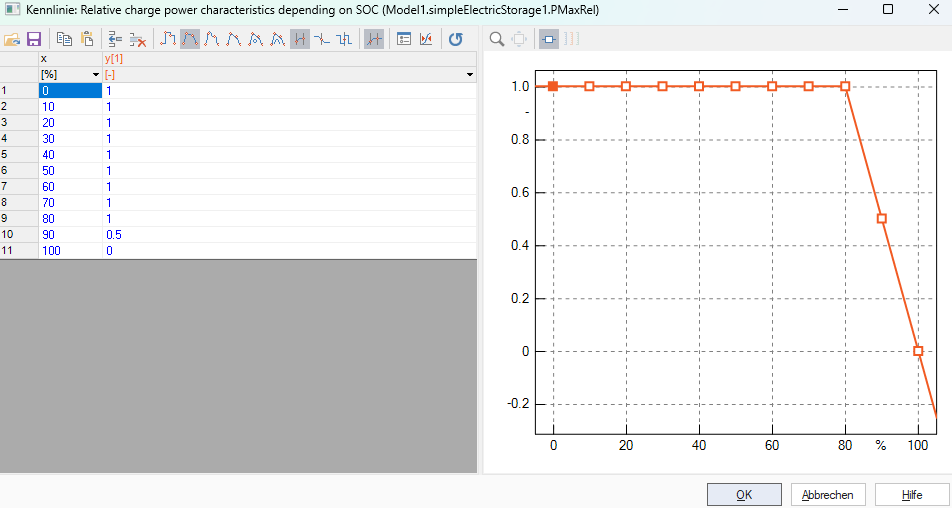
The SimpleElectricStorage model get a reference power value ▶PRefStorage sets the charging or discharging power of the model. A positive power value is defined as discharging of the storage and positive is charging. To set the technical electrical storage specifics the maximum storage power (charging) is defined by PMaxCharge, the minimum storage power (discharging) by PMinDisCharge and the storage capacity by Capacity. At last a charging/discharging power curve is defined to adjust the storage model to storage specific behavior. For the charging power curve the parameter PMaxRel must be defined with the table (see figure below) and the discharging power curve PMinRel is defined similar to PMaxRel.
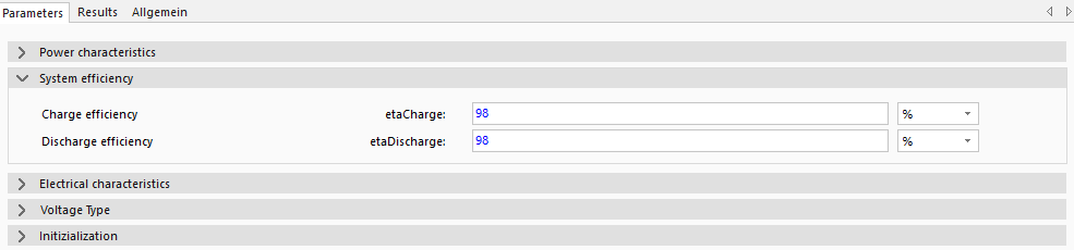
In the figure above, the charging and discharging efficiencies (Charging etaCharge and Discharging etaDischarge) of the storage tanks are set. A charging efficiency etaCharge of 98% means that 98% of the charged energy arrives in the electrical storage unit and 2% is lost.
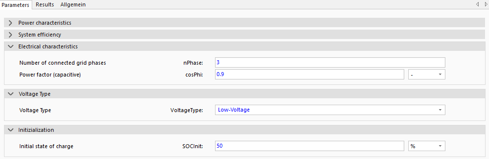
To set the grid parameters, the number of grid phases nPhase (either 1 phase or 3 phases), the capacitive power factor cosPhi (AC efficiency/proportion of active to apparent power) and the voltage level VoltageType are set in the Electrical characteristics group. For the Basic variant, the number of phases is set to 3 and the voltage level VoltageType is set to Low-Voltage. As an alternative for the voltage levels VoltageType, there are also the variants Medium-Voltage and High-Voltage, which allow a finer simulation of the electrical connections. The respective voltage levels can only be connected to the connectors of the same voltage level. The ▶LVGrid3 connector of the 3-phase power connection of the battery must then be connected to the electrical AC grid of the model Grid. The initial state of the electrical storage is defined by the initial SoC SOCInit and measure the energy charged in the electrical storage at the beginning of the simulation.
1-Phase Grid Connection
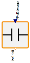
For the 1 phase grid connection the parameter nPhase gets changed to 1 to better model the connection of the SimpleElectricStorage for only one phase which allows a more granular definition of the electrical grid, e.g. check for overload on a specific phase. To connect the SimpleElectricStorage with the AC grid Grid it must be defined which phase of the 3-phase grid will be used (see PhaseTap).
Model Background
Calculation Of Current Storage Charging Power
The current power of the battery PStorage gets defined by the following equation using the reference power PRefStorage, the maximum possible charging power of the battery at the current SoC