HeatPump
Symbol | 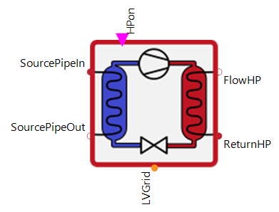 |
|---|
Use
Heat pumps are devices that transfer thermal energy from a source to a sink that is at a higher temperature than the source. To provide usable thermal energy they use electrical energy which is converted into mechanical work for example by compressors. For industrial applications environmental heat sources with high energy density are most commonly used (e.g. groundwater, river water, ground).
The HeatPump covers the following applications:
Basic: A switch-on and switch-off signal is provided to the HeatPump, so it is either on at full power or completely off. The maximum heat power and the COP are defined by the input curves and depending on the flow temperatures at the heat and source side.
Modulation: The heat output of the HeatPump is additionally modulated, so it is not only switched on and off, but can also only call up part of its maximum output during operation.
Cascade: This assumes that the HeatPump has several generator stages (compressors) or that there is a cascade of HeatPumps. These are used one after the other depending on the input signal ▶CompNumb.
Parameters and Connectors
Basic
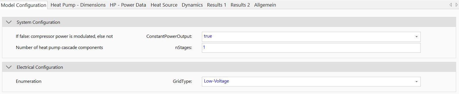
The heat pump is connected to the heat sink side with the connectors ▶FlowHP and ▶ReturnHP. The heat source side is linked by the ▶SourcePipeIn and ▶SourcePipeOut connector. The on/off signal is provided via ▶HPon and the calculated power demand to ▶LVGrid. The type of grid connector can also be specified depending on which GridType (i.e. 'Low-Voltage', 'Medium-Voltage' and 'High-Voltage') should be used to operate the heat pumps internal compressor.
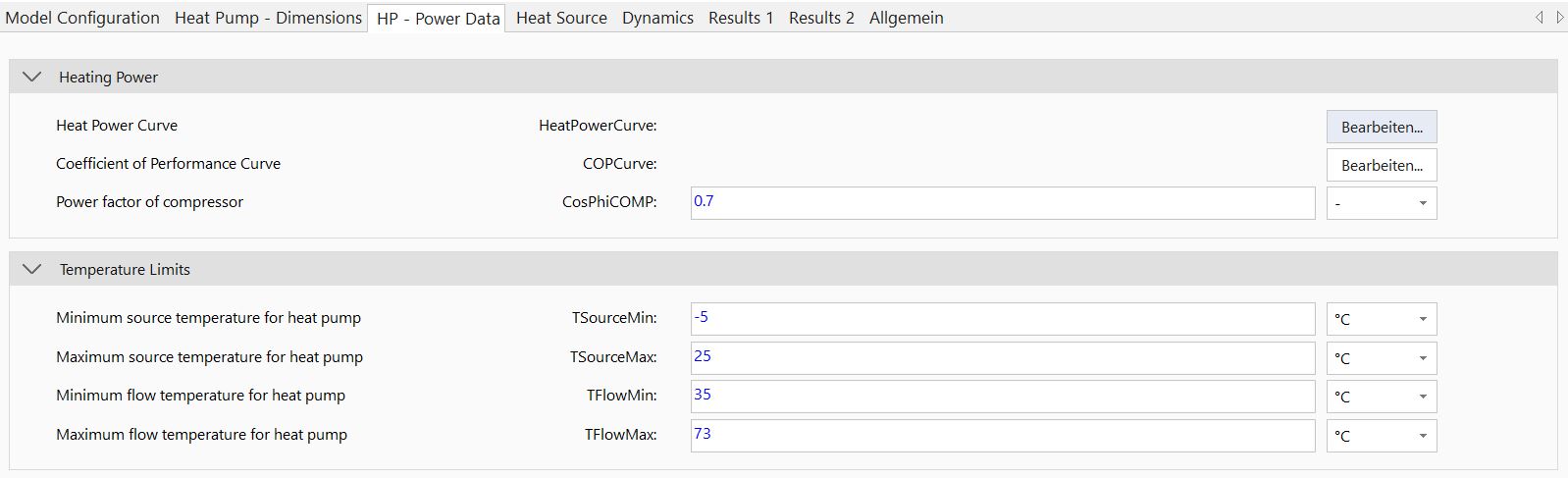
The heat power output is simplified calculated using measurement data of heat pump system. Based on this the heat power output and coefficient of performance (COP) of the system are characterized dependent on heating system flow and heat source temperature. The associated curves can be adapted using the table dialog of parameter HeatPowerCurve and COPCurve. To prevent these tables from being extrapolated too far, the minimum and maximum temperatures (TSourceMin, TSourceMax, TFlowMin and TFlowMax) must be set. In order to correctly map the electricity demand of the heat pump, the power factor of the compressor (CosPhiCOMP) must also be set accordingly.
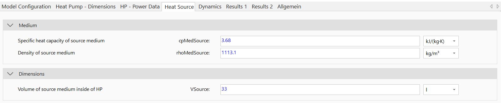
It is also important to parameterise the properties of the source medium (cpMedSource, rhoMedSource) correctly. Inertia can be modelled with the help of the source volume (VSource).
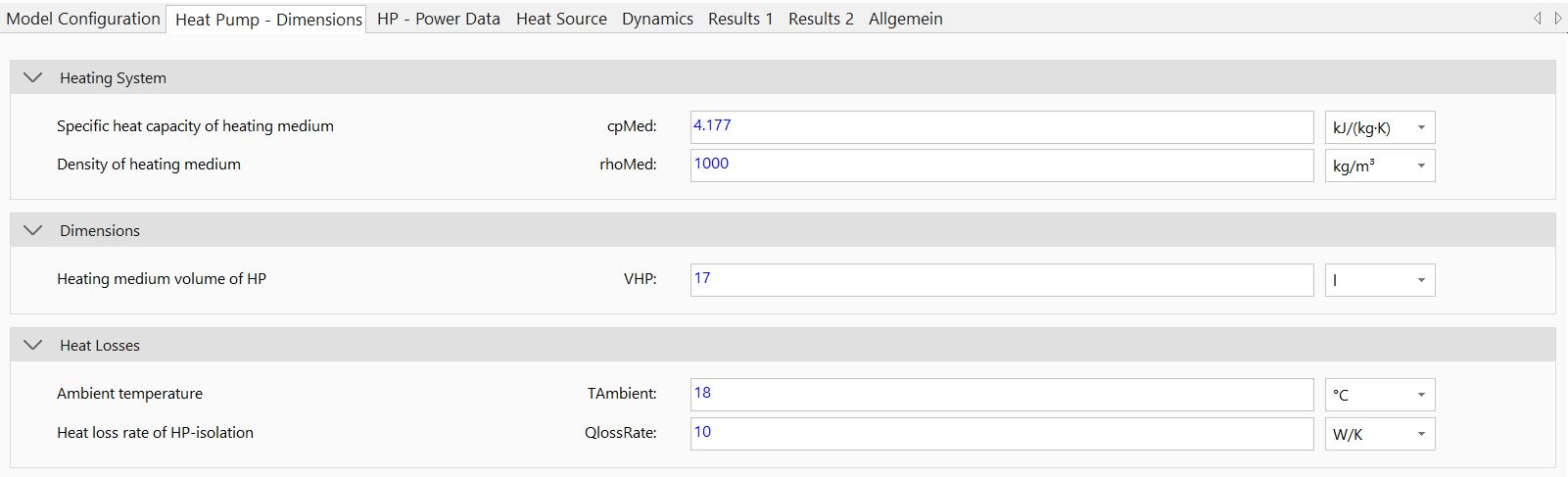
The properties (cpMed, rhoMed) and volume (VHP) of the heat transfer medium on the sink side must also be parameterised correctly. In addition, internal heat losses in the heat pump can be mapped via TAmbient and QlossRate.

The internal dynamics of the model regarding heat production (tHPStart) can also be adapted. If specific data for this is not available, the pre-defined parameters should be used.
Modulation
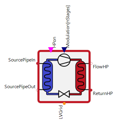

To only call up part of the heat pump's maximum heat output during operation, the parameter ConstantOutput can be set to false. Afterwards, the connector ▶Modulation is available. This can be used to signal the percentage of maximum power to be called up. No more than 100 % is possible. The technological limit of the minimum modulation (RelModMin) is also taken into account.
Cascade
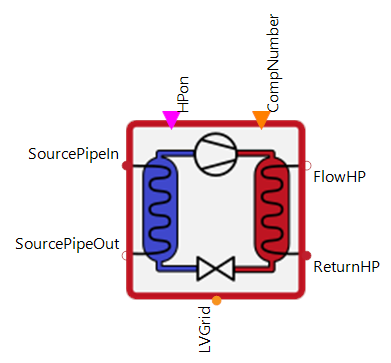
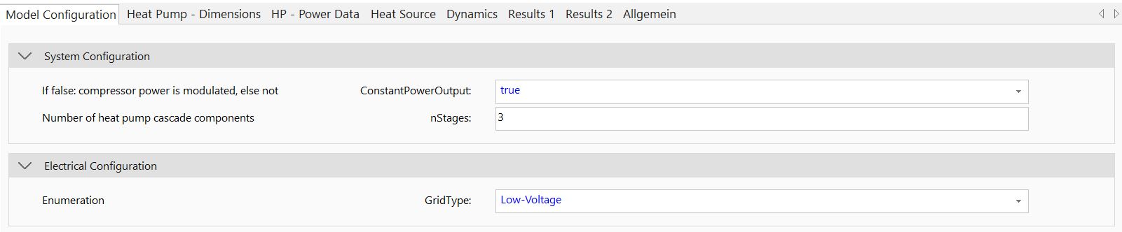
Important to note is that when parameterizing cascaded heat pump systems the parameter nStages is used to describe the number of cascaded steps. If this number is greater than 1, the connector ▶CompNumber is released. This can be used to control the active number of stages.
In general, the total heat power must be specified in the HeatPowerCurve. As an example, if the data sheet of a heat pump unit is available and two stages are required, the outputs in the data sheet must be multiplied by 2 and inscribed in the HeatPowerCurve table, accordingly.
Model Background
Due to heat pump system complexity when compared to other heating systems (e.g. condensing boilers or CHPs) simplification was necessary to reduce simulation time. Heat power output highly depends on inner system states and medium characteristics. To reduce model complexity, inner system processes were neglected completely. The heat power output is instead, calculated using measurement data of heat pump system. This data is commonly available from the manufacturer for heat pump systems. Based on this, the heat power output and coefficient of performance (COP) of the system are characterized dependent on heating system flow and heat source temperature. As a result of this approach, the source pump does not adequately interact with the corresponding heat pump system. The pump however has a non-neglectable power demand and is thus externally modeled as an additional electrical energy consumer.