Photovoltaic
Symbol |  |
|---|
Use
This model represents a scalable photovoltaic model. Photovoltaic systems use solar radiation as an environmental energy source to produce electrical energy. In this process, they act as a DC-voltage source. To feed the local grid with renewable energy produced by a photovoltaic system, a conversion from DC-voltage into AC-voltage is necessary. Therefore, two PV-converter systems are provided within the sub-package Controller.
Parameters and Connectors
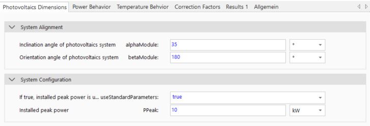
The photovoltaic model has to be connected with the Environment model via the ▶EnvironmentConditions to get the information about radiation and ambient temperature. The generated electrical power can be transferred and used via the ▶DC connector. The PV system to be modeled should be configured within the parameter dialog. Here, the systems inclination (alphaModule - 90° vertical, 0° lying flat) and orientation angle (betaModule - 0° North, 90° East, 180° South, 270° West) have to be defined. The installed peak power (PPeak) is a decisive parameter.
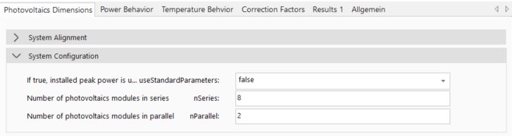
If a specific system configuration is to be simulated, the parameter useStandardParameters can be set to 'false'. Then the number of connected PV modules (nSeries and nParallel) can then be parameterized. Note that modules connected in series increase the overall system voltage. Modules connected in parallel, on the other hand, increase current output of the PV system.
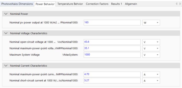
To enable an easy model parameterization with standard data sheet values for voltage and current behavior of a PV system, parameters for open-circuit-voltage (VocNominal1000), MPP voltage (VMPPNominal1000), short-circuit-current (IscNominal1000) and MPP current (IMPPNominal1000) must be defined. Also, the nominal power output (PNominal1000) and the maximum system voltage (VMaxSystem) has to be parametrized. The necessary values and characteristics can be found in corresponding PV module data sheets.
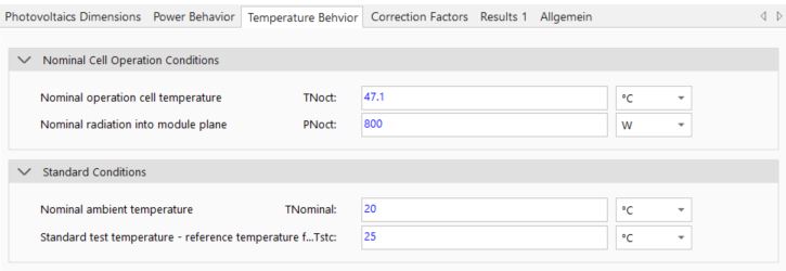
Different photovoltaic module temperatures can cause differing system behavior. Therefore, a module temperature simulation is necessary. Note that a dynamic collector temperature simulation is not conducted so as to reduce simulation time. Instead, standard data sheet values (NOCT - Normal Operating Cell Temperature) are used in the model for module temperature calculation. Therefore, the nominal cell operation conditions (TNoct, PNoct) and standard conditions (TNominal, Tstc) have to be defined.
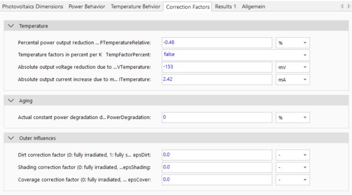
In general, module-temperature-specific power and voltage decrease and current increase (cf. temperature-specific behavior of semi-conductor materials). This is specified by the parameters PTemperatureRelative, VTemperature and ITemperature. If the last two parameters are to be set as relative values, the parameter TempFactorPercent must be activated. Additional effects on electrical power reduction, such as module aging, can also be simulated. Concretely for this, the percentage PowerDegradation-factor must be specified. Normally, power degradation amounts to about 1% a year (PowerDegradation should thus be set to -1%). Ensure that all algebraic signs are set correctly.
Influences of additional shading by surrounding objects (epsShading - e.g. buildings, trees etc.), dirt (epsDirt) and snow (epsCover), can be considered statistically. These factors thus stay constant over the whole simulation time period. For annual simulations, special conditions like snow lying on the collector should be defined with an appropriate correction factor. As an example, if there is snow present for 1 day a year on the collector, the corresponding correction factor should be set to 1/365.
Model Background
Electrical Calculation Approach
The model itself calculates the system states for a single module and scales the results according to the defined system configuration. To simulate the electrical behavior of a PV system, a 1-diode-model is implemented. This model enables the simulation of the characteristic voltage and current behavior of a PV module dependent on solar radiation. Here, the forward resistance Ron and backward conductance Goff are calculated internally.
Calculation Module Temperature
Different photovoltaic module temperatures can cause differing system behavior. Therefore, a module temperature simulation is necessary. Note that a dynamic collector temperature simulation is not conducted as to reduce simulation time. Instead, standard data sheet values (NOCT - Normal Operating Cell Temperature) are used in the model for module temperature calculation: