AbsorptionCooling
Symbol | 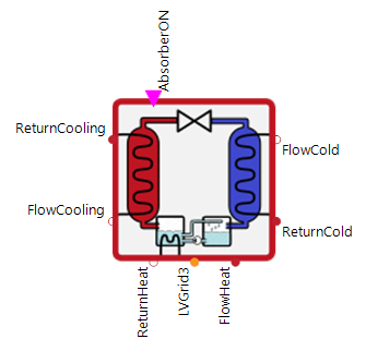 |
|---|
Use
The AbsorptionCooling is a type of heat pump that transfers thermal energy from a source to a sink. The sink has a higher temperature than the source. Conventional heat pumps transfer the heat energy to a higher level with the help of an electrical driven compressors. The absorption heat pump, on the other hand, uses the principle of absorption to compensate for the electrical energy requirement of a compressor by applying the concept of high-temperature heat absorption.
The AbsorptionCooling covers the following applications:
Basic: AbsorptionCooling receives an on/off signal so that it is either switched on at full power or switched off completely. The thermal power consumption and the COP are defined by the input curves and depending on the flow temperatures on the heat and source side.
Modulation: The cooling power of the AbsorptionCooling is additionally modulated, so it is not only switched on and off, but can also only call up part of its maximum output during operation.
Cascade: This assumes that the AbsorptionCooling has several generator stages (absorbers) or that a cascade of AbsorptionCooling machines is available. These are used one after the other depending on the input signal ▶CompNumb.
Parameters and Connectors
Basic
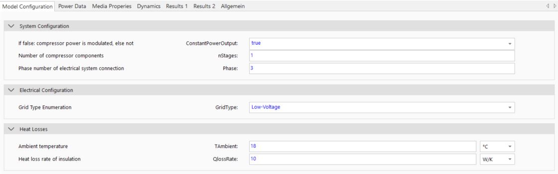
In order to be able to use the principle of an absorption cooling machine, the connectors ▶FlowHeat and ▶ReturnHeat should supply the required high-temperature heat. The connectors ▶FlowCooling and ▶ReturnCooling are used to condense the working gas and therefore represent the heat sink. They should be connected to a cooling system such as 'DryCoolingTower' or 'HybridCoolingTower'. The two connectors ▶FlowCold and ▶ReturnCold provide the low-temperature volume flow, which can be used in a cooling system e.g. cooling a building. The on/off signal is supplied via ▶AbsorberON and the calculated power demand to ▶LVGrid. The type of grid connector can also be specified depending on the GridType (i.e. 'Low-Voltage', 'Medium-Voltage' and 'High-Voltage') with which the heat pumps internal fluid pump is to be operated, as well as the number of the phases (Phase). In addition, the internal heat losses of the absorption cooling machine can be mapped via TAmbient and QlossRate.
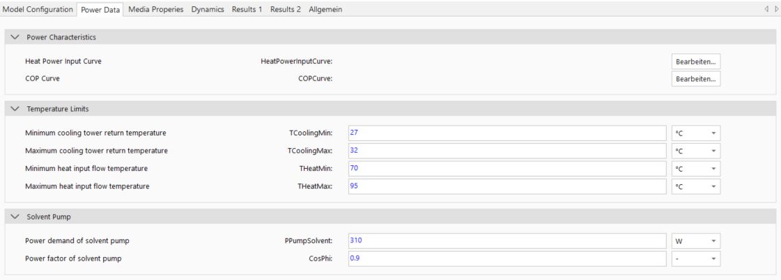
The cooling power output is simplified calculated using measurement data from the heat pump system. Based on this, the heat power consumption and coefficient of performance (COP) of the system are characterized as a function of the high-temperature heat system flow and heat sink temperature. In this case, the COP describes the ratio between the high temperature heat and the cold output. The associated curves can be adjusted via the table dialog of HeatPowerInputCurve and COPCurve parameters. To prevent these tables from being extrapolated too far, the minimum and maximum temperatures (THeatMin, THeatMax, TCoolingMin and TCoolingMax) must be defined. The power factor (CosPhi) and the power demand (PPumpSolvent) of the internal fluid pump must also be set accordingly in order to correctly map the power requirement of the heat pump.
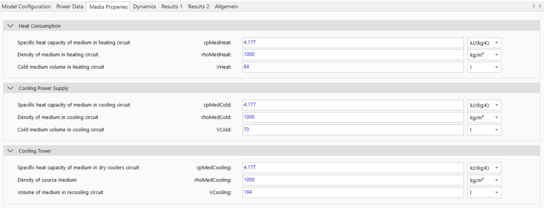
It is also important to correctly parameterize the properties of the medium in the cooling circuit (cpMedCold, rhoMedCold), in the heating circuit (cpMedHeat, rhoMedHeat) and in the local recooling circuit (cpMedCooling, rhoMedCooling). The inertia can be modeled via the volumes (VHeat, VCold and VCooling).

The internal dynamics of the model in relation to heat production (tAbsorberStart) can also be adjusted. If no specific data is available for this, the predefined parameters should be used.
Modulation
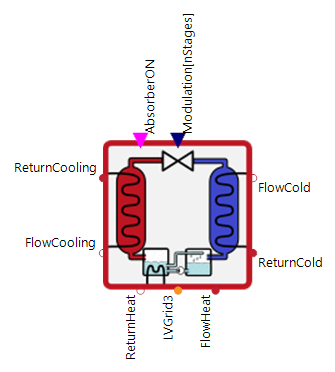
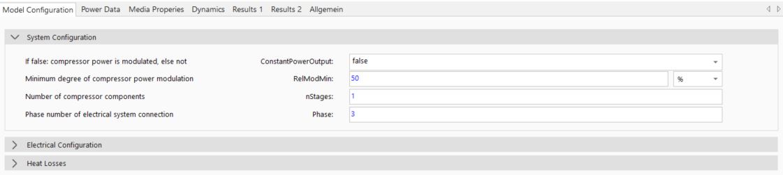
To call up only part of maximum heat output of the heat pump during operation, the ConstantOutput parameter can be set to false. The connector ▶Modulation is then available. This can be used to signal the percentage of the maximum power to be called up. More than 100 % is not possible. The technological limit of the minimum modulation (RelModMin) is also taken into account.
Cascade
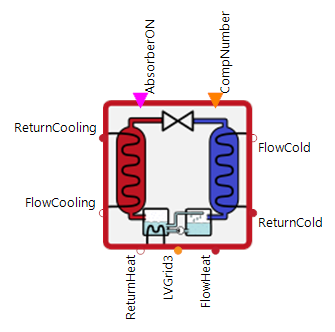
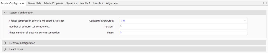
When parameterizing cascaded heat pump systems, please note that the parameter nStages describes the number of cascaded stages. If this number is greater than 1, the connector ▶CompNumber is activated. This allows the active number of stages to be controlled.
In general, the total heat power input must be specified in the HeatPowerInputCurve. As an example, if the data sheet of an absorption cooling unit is available and two stages are required, the values in the data sheet must be multiplied by 2 and entered accordingly in the HeatPowerInputCurve table.
Model Background
Specifically, the medium is first absorbed by water and pumped to a high pressure level using a simple fluid pump, whereby significantly less electrical energy is required than when compressing a gaseous medium. At the higher pressure level, the gas can be released by supplying thermal heat (i.e. by boiling).
Due to complexity of a heat pump system compared to other heating systems (e.g. condensing boilers or CHPs), a simplification was necessary to reduce simulation time. The heat power input depends heavily on the internal system states and properties of the medium. In order to reduce the complexity of the model, the internal system processes were completely neglected. Instead, the heat power input is calculated using measured data from the heat pump system. This data is usually available from the manufacturer. Based on this, the heat power input and coefficient of performance (COP) of the system are characterized as a function of the (local) cooling system flow and high-temperature heat source temperature.