Cogeneration
Symbol | 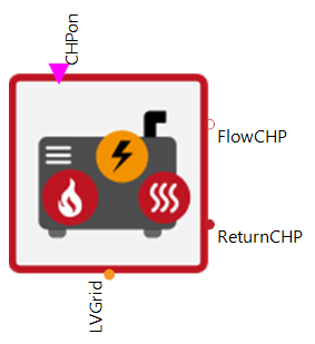 |
|---|
Use
Combined heat and power units (CHPs) are modular devices for heat and electricity production. They can be controlled using external controllers, prioritizing either heat or electricity production. CHPs produce electricity with an internal combustion engine that drives a generator. In this process, excess thermal energy is used for heating. This way, the efficiency of heat and electricity production can be increased.
The Cogeneration covers the following applications:
Basic: A switch-on and switch-off signal is provided to the CHP, so it is either on at full power or completely off. The power output and efficiency are defined by the input curves and depending on the flow temperatures at the heating circuit.
Modulation: The heat and power output of the CHP is additionally modulated, so it is not only switched on and off, but can also only call up part of its maximum output during operation.
Cascade: This assumes that the CHP has several generator stages (burners) or that there is a cascade of CHPs. These are used one after the other depending on the input signal ▶ActiveUnits.
Parameters and Connectors
Basic
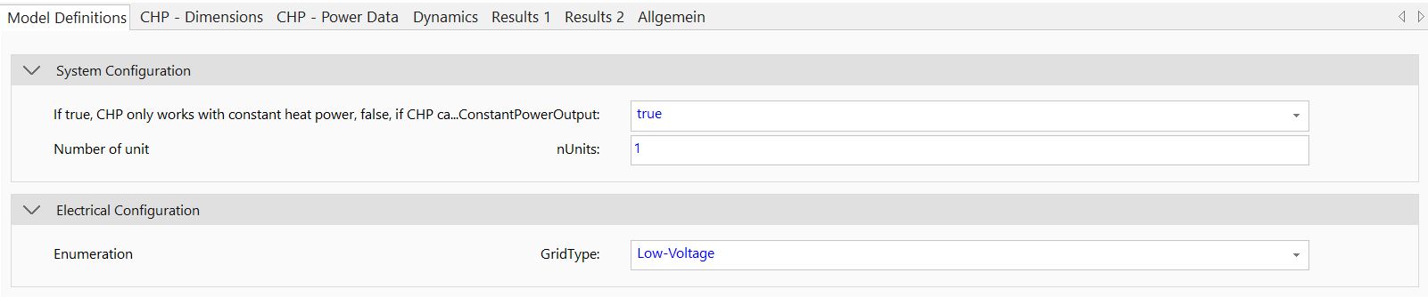
The CHP is connected to the heating circuit via ▶FlowCHP and ▶ReturnCHP. It is turned on via a 'true' signal at the ▶CHPon input. The co-generation plant is able to feed into a low, medium and high voltage grid. This can be specified using the GridType parameter.
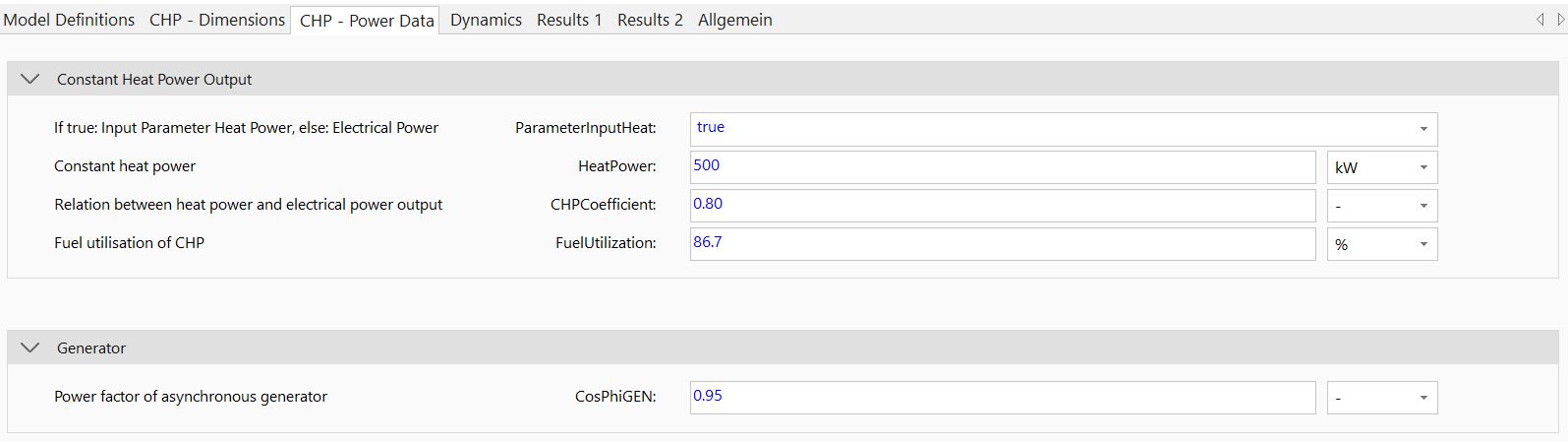
The CHP size can be adjusted in two ways: With a nominal heat power or electrical power. This can be set via the parameter ParameterInputHeat and should be based on the available data. In case of the heat parameters, the constant HeatPower, the CHPCoefficient and the FuelUtilization coefficient can be specified. In case of the electrical parameters, the electrical and thermal power is defined by the ElectricalPower. In order to map the electricity production correctly, the power factor of the generator (CosPhiGEN) must also be set.
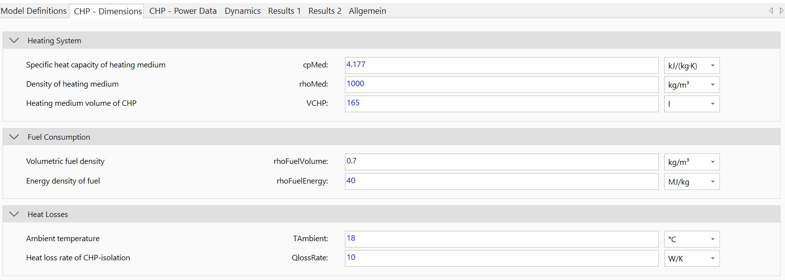
The parameterization of fuel type is done within the parameter dialog via volumetric (rhoFuelVolume) and energy density (rhoFuelEnergy) of the used fuel. Normally, this can be Bio-gas, natural gas, diesel or benzine. The properties (cpMed, rhoMed) and volume (VCHP) of the heat transfer medium on the sink side must also be parameterised correctly. In addition, internal heat losses in the heat pump can be mapped via TAmbient and QlossRate.
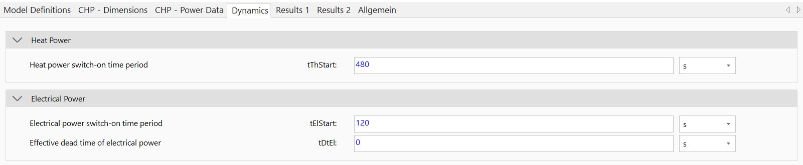
The internal dynamics of the model regarding heat (tThStart) and electricity (tElStart, tDtEl) production can also be adapted. If specific data for this is not available, the pre-defined parameters should be used.
Modulation
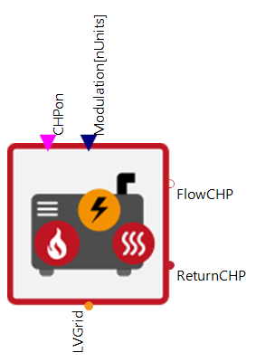

If the parameter UseConstantPowerOutput is set to 'false' the model represents a CHP whose heat and electrical power output is modulated continuously. The technological limit of the minimum modulation (RelModMin) is also taken into account.
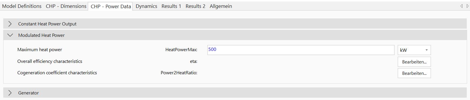
With modulation, the maximum heat power (HeatPowerMax - ParameterInputHeat set to 'true') or electrical power (ElectricalPowerMax - ParameterInputHeat set to 'false') output has to be set. Also, the corresponding CHP data curves for eta and the Power2HeatRatio, depending on the flow temperature, have to be adapted.
Cascade
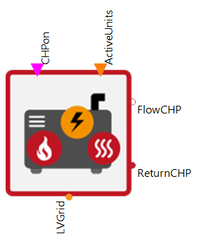

Important to note is that when parameterizing cascaded boiler systems the parameter nUnits is used to describe the number of cascaded steps. If this number is greater than 1, the connector ▶ActiveUnits is released. This can be used to control the active number of stages.
In general, the total heat or electrical power must be specified in the HeatPower/ElectricalPower. As an example, if the data sheet of a CHP unit is available and two stages are required, the outputs in the data sheet must be multiplied by 2 and inscribed in the HeatPower/ElectricalPower parameter, accordingly.
Model Background
The definition of the Power2HeatRatio/CHPCoefficient is as follows: