ChargingStation
Symbol | 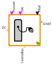 |
|---|
Use
Recommendation: Use ACChargingStation model instead! It is the further development of this model.
The charging station model simulates a single charging point where only one vehicle can be charged (or discharged) at a same time. It can be an AC or DC charging point with any charging power.
Important: The charging station model does not differ between AC and DC charging because the charging station simulates the entire charging technology for charging a vehicle's battery. The vehicle simulates only the vehicle battery but not the on-board charger:
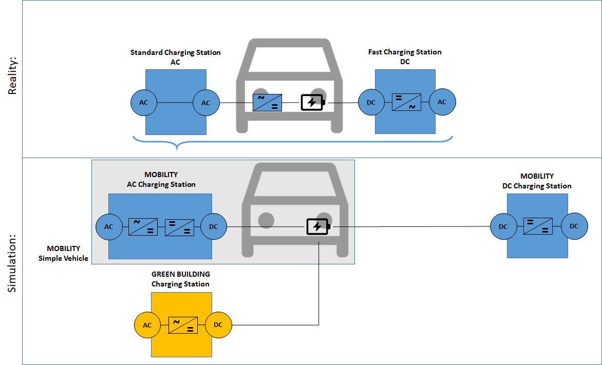
Reality: In reality, there is AC and DC charging. The main difference between AC and DC charging is where the alternating current (from the power grid) is converted into direct current (for charging the batteries). With AC charging, the conversion takes place in the vehicle itself. Electric vehicles have a built-in converter, a so-called on-board charger, which takes the alternating current and converts it into direct current via several converters. When charging at a DC charging point, the on-board charger can be bypassed because there is a current transformer in the charging station itself.
Simulation: For the simulation, it is assumed that the entire charging technology is located in the charging station and not in the vehicle. The on-board charger is part of the charging station model and therefore the vehicle is only charged with direct current.
Parameters and Connectors
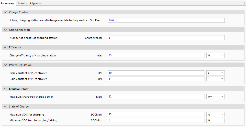
The charging station model is necessary to couple an electric vehicle (BEV or PHEV) with the AC-grid ▶Grid3 of the building. In this regard a 3-phase ChargePhase=3 or single-phase ChargePhase=1 grid connection can be defined.
▶DC is the direct current connection between the vehicle and the charging station and the charging station controls the charging process of the vehicle via ▶ControlBus.
A charging (or discharging GridFeed=true) process can only be simulated if a vehicle is ▶Present at the charging station and the charging station is switched-on ▶ON. The reference charge (and discharge) power ▶PRef must be controlled by external controllers dependent on inner building energy system states (e.g. renewable energy availability or simulated electricity prices). If ▶PRef>0, the vehicle is charged and if ▶PRef<0, the vehicle is discharged.
Model Background
Internally, the model either uses a B6- or B2-converter model. If the related maximum battery voltage exceeds a value of 0.9 times the effective grid voltage, the battery converter must be defined as a 3-phase ChargePhase=3 converter. The maximum voltage of 3-phase converter is 2.34 times the effective grid voltage. Note that using a battery converter model as a single-phase converter, avoids high reactive power demands for voltage conversion.
The battery converter itself acts as a PI-controller which controls charge and discharge power via intermediate-circuit voltage on the vehicle-side, dependent on reference power. Ensure that all connectors are defined with correspondent battery characteristics, to avoid numerical problems.