BEV
Battery Electric Vehicle
Symbol |  |
|---|
Use
The battery electric vehicle (BEV) simulates the charging/discharging processes of the vehicle's battery and the use of the vehicle while driving. When is the vehicle at the charging station and when is it driving around? What is its state of charge on arrival?
Important: The vehicle simulates the vehicle's battery but not the on-board charger:
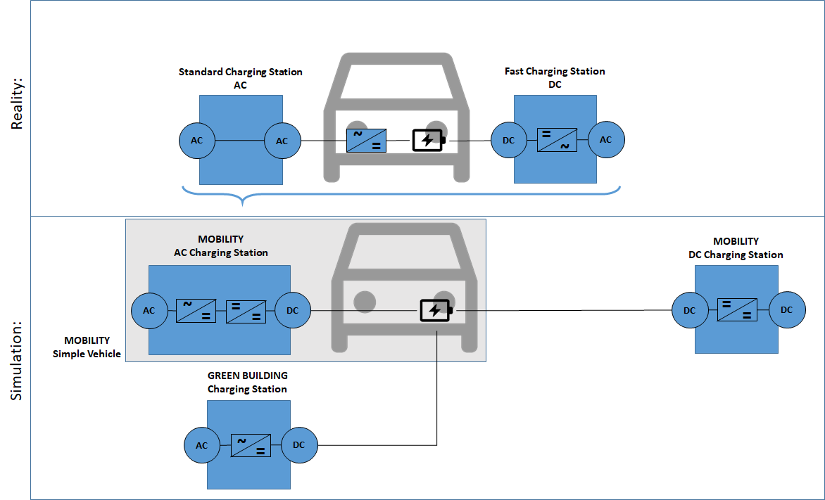
Reality: In reality, there is AC and DC charging. The main difference between AC and DC charging is where the alternating current (from the power grid) is converted into direct current (for charging the batteries). With AC charging, the conversion takes place in the vehicle itself. Electric vehicles have a built-in converter, a so-called on-board charger, which takes the alternating current and converts it into direct current via several converters. When charging at a DC charging point, the on-board charger can be bypassed because there is a current transformer in the charging station itself.
Simulation: For the simulation, it is assumed that the entire charging technology is located in the charging station and not in the vehicle. The on-board charger is part of the charging station model and therefore the vehicle is only charged with direct current.
Parameters and Connectors
Connectors
The vehicle can be connected to different charging station models (ACChargingStation, DCChargingStation, GB_ChargingStation). ▶DC is the direct current connection between the vehicle and the charging station and the charging station controls the charging process of the vehicle via ▶ControlBus.
▶Present and ▶Driving have to be supplied to the vehicle model. If ▶Present is True, the vehicle is connected to the charging station. If ▶Present is False, ▶Driving has to be True because the vehicle is driving.
Note: You can easily define a presence or driving profile, for example depending on the HourOfDay and DayOfWeek by using the results of the environment model Environment.
Parameters
Battery
The electric vehicle model consists of a highly dynamic, battery cell impedance model that includes the following components:
Variable voltage source (dependent on SoC) representing the open-circuit-voltage
Internal ohmic resistance (dependent on cell temperature and SoC)
Constant-phase-elements (dependent on cell temperature and SoC) representing high and low internal resistance dynamics
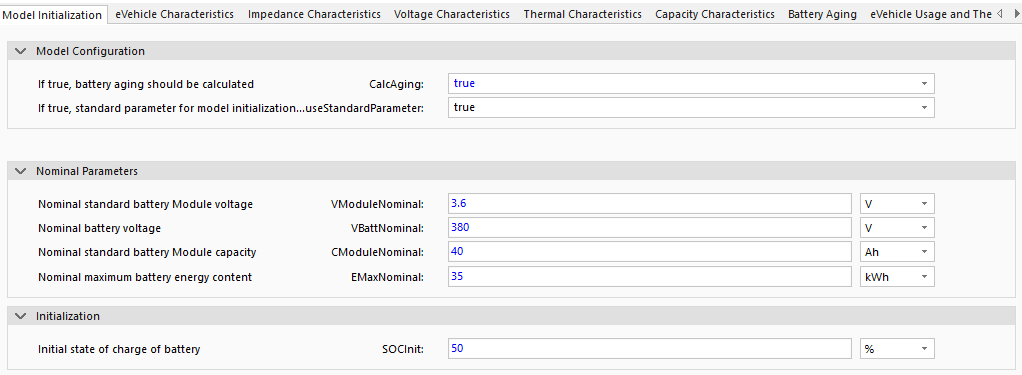
Due to simulation time reduction being a pivotal characteristic for model usability, the battery is modeled as a free-parameterizable number of battery cells or modules. It is assumed that all cells or modules show the same behavior. The user can parameterize cell specifications via useStandardParameter (i.e. number of cells or modules in series and parallel) manually, using the parameter dialog or use the pre-defined standard parameters (i.e. battery voltage, capacity). For the latter, the correct cell number is calculated internally before simulation begin, using standard battery cell parameters contained in the model data directory. The model can model either lithium-ion or lead-acid batteries using this default data (...\GreenCity\Data\ModelData\battery) . If you want to change the battery type, you must adjust ImpedanceFile, VocFile, QRealFile and AgingFile. Change LiIon to Pb everywhere. If a special type of battery cell or module is to be simulated, additional battery data can be imported into the model data directory, using the data file as a template. Add a new folder next to LiIon and Pb (...\GreenCity\Data\ModelData\battery) and add the same folder structure as in LiIon and Pb.
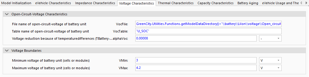
For the simulation the maximum (VMax) and minimum (VMin) voltage of the modeled battery cell or module must also be declared. This is necessary to parameterize the battery converter model with the maximum and minimum permitted battery voltages. This ensures that the battery will not be over-charged or deep discharged during the simulation. Therefore, it is necessary to connect the ▶ControlBus to the charging station model to avoid numerical difficulties. For li-ion-cells the voltage range of 3.0V and 4.2V is normally used dependent on the open-circuit-voltage data. For lead-acid-battery modules this range is between 11.8V and 12.8V.
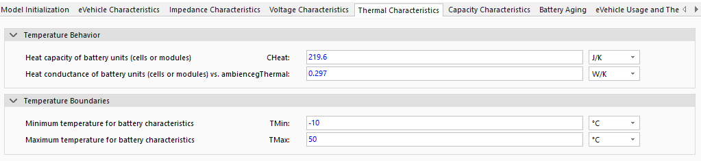
To avoid linear interpolation errors it is necessary to parameterize the minimum (TMin) and maximum (TMax) temperature which are used to define battery specifications in the model data directory.

The real capacity can differ from nominal cell capacity, dependent on production process related deviations. If the battery model is to be parameterized manually (i.e. number of cells) measurement data for cell or module capacity can be used as an input parameter QRealFile. In the case of automated cell parameterization (useStandardParameter = true) the real capacity is set to nominal as it is assumed that detailed information of the cells is not available. Input data for maximum QMaxTable and minimum QMinTable capacity describe nominal differences of cell or module capacities regarding different temperatures. This data is normalized with 25°C as a reference.

Battery aging can be modeled considering simulated battery temperature, overall capacity and cycling. If the parameter CalcAging = true, the battery aging model will be automatically included into the simulation process. Here battery aging data contained in the model data directory is used. The model additionally allows for analysis extension using specialized battery aging data. Such a process however, demands extensive measurement data. The output of the battery aging simulation is internally converted to the SOH-value (state of health) either dependent on cyclization or capacity. SOH is always initialized with 100%. It is thus assumed that the simulated battery is new when the simulation begins. In general, a battery reaches its end of life when the SOH drops below 80%.
The State of function (SOF) is an additional simulation result which combines battery aging and actual temperature to a single value, representing the actual usability of the simulated battery. Note that the temperature-specific capacity losses, in this process, are reversible.
Vehicle dynamics and electricity demand
When a vehicle drives it can logically not be present at a charging station. The electricity demand of electric vehicles can thus be calculated independently of the modeled building energy system. For this, it is only necessary to determine which state of charge (electricity demand) the vehicle's battery has, once the electric vehicle returns to the charging station.

In this regard, it is necessary to model how much energy is needed to drive the vehicle, the desired distance. Here a quasi-static approach is applied. Due to the building energy system behavior and vehicle energy demand for driving being independent of each other, the drive-cycle specific average velocity and electrical power demand are included in the BEV-model as constant parameters. It is thus assumed that the vehicle moves with a constant average velocity vCycleAverage and electrical power demand PBattCycleAverage. These two values could be calculated in more detail during pre-processing using dynamic simulation or quasi-static calculation approaches. This assumption also helps to reduce simulation time which is a main requirement in model development.
Applying such an approach, allows for the inclusion of detailed drive-cycle data for electrical power demand, into the simulation process without increasing model complexity and resultant simulation time. To ensure correct simulation the time-dependent characteristics for vehicle ▶Present ('true' when present) at charging station and ▶Drive ('true' when vehicle is driving) have to be supplied to the model.
In general, the electric vehicles return to the charging station with an SOC between 0 and 100%. If the capacity of a vehicle battery is too low to fulfill mobility demand (i.e. simulated driven distance is longer than maximum range), the vehicle returns to the charging station with an empty battery. It is thus assumed that additionally needed electrical energy is provided by external charging stations which do not interact directly with the modeled building energy system. Note that the additionally required energy cannot be considered within the presented simulation model.
Air conditioning and heating
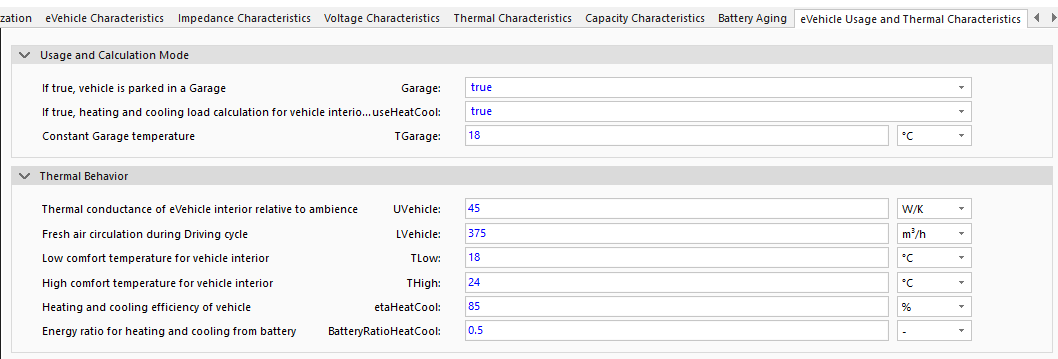
Besides the power demand for driving, interior air conditioning and heating are two of the most important influences on overall energy consumptions of vehicles. To consider this the vehicle cabin is modeled as thermal one-zone-model. Concretely, heat losses and gains through the shell via heat transmission (UVehicle) and ventilation (LVehicle) dependent on the ambient temperature, are considered and simulated. According to the temperature difference between low TLow and high THigh comfort temperatures the heating or cooling load is calculated.
Electric vehicles provide this thermal energy demand using the electric energy of the battery. This energy conversion is defined by a specific system efficiency (etaHeatCool). Note that if a heat pump system is used the efficiency can be set to a value greater than 1 (usually between 1 and 4). That way the COP (coefficient of performance) of heat pump systems can be modeled. If there are other additional heat sources (e.g. heat losses of electric motor etc.) the parameter BatteryRatioHeatCool can be set to a value lower than one. It is thus possible to adapt the electrical energy demand for heating and cooling with an additional statistical factor.
All other parameters that are not explained should only be adjusted if measured values are available. If no measured values are available, retain the default values.