HeatingUnitFlowTemperature
Symbol | 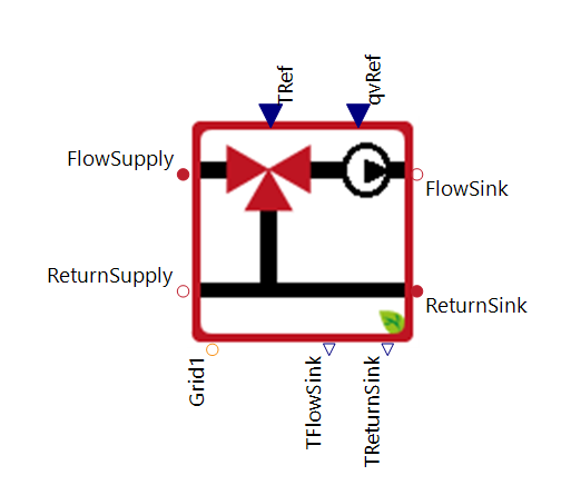 |
|---|
Use
This HeatingUnitFlowTemperature component regulates the flow temperature to the heat sink via an internal circulation pump, the heat supply, the flow temperature, and the return temperature of the heat sink. It can also be used to define the flow temperature and the total volume flow for several heating systems connected in series or in parallel.
Basic: UsePowerCalcPump = true. Enables the electrical power calculation for the circulation pump.
Simple: UsePowerCalcPump = false. Disables the electrical power calculation for the circulation pump.
Parameters and Connectors
Basic
▶FlowSupply refers to the flow coming from the supply side. At this point, the heating fluid, including its temperature and volume flow, is transferred into this model.▶ReturnSupply represents the return flow back to the heating supply. Here, the cooled fluid is directed back to the storage system or heater.
▶FlowSink refers to the flow going to the sink side. At this point, the heating fluid, including its temperature and volume flow, is transferred out of this model. ▶ReturnSupply represents the return flow back from the heating sink side. Here, the cooled fluid is coming back from the heating zone.
▶qvRef refers to the reference volume flow of the heat sink, which is typically defined by a heating controller VolumeFlowControllerHeatingSystem. ▶TRef refers to the reference temperature of the heating unit. ▶TFlowSink describes the actual flow temperature of the sink. ▶TReturnSink describes the actual return temperature of the sink. Both outputs are required by the heating controller VolumeFlowControllerHeatingSystem.
▶Grid1 is a connection for a single-phase power grid. The internal electric circulation pump requires a power supply via an external grid connection (single-phase or three-phase).
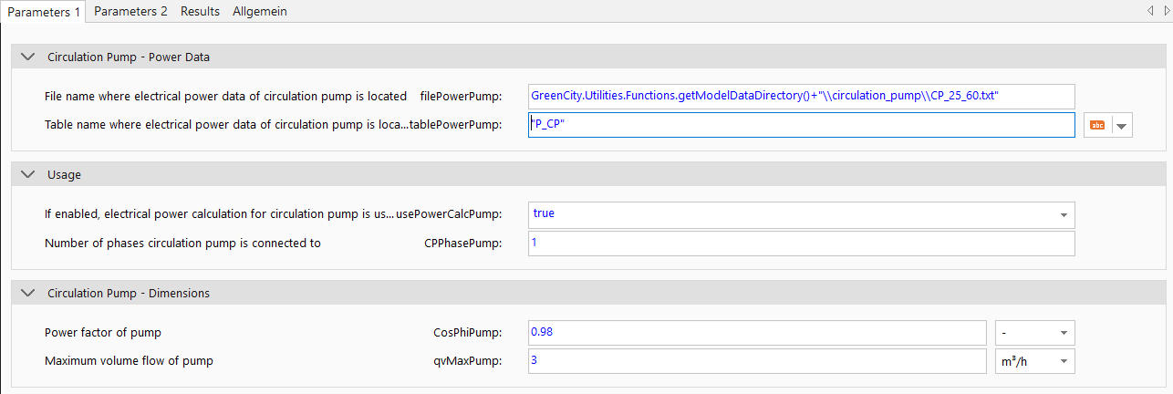
The parameters for the electrical consumption of the pump must then be set in the parameter dialog. These include the file path filePowerPump, the table name tablePowerPump, the phase CPPhasePump and the power factor CosPhiPump. A detailed explanation can be found in the documentation for the pump component. The maximum volume flow qvMaxPump of the pump must also be set accordingly.
UsePowerCalcPump = true. Enables the calculation of electrical power for the circulation pump. CPPhasePump specifies the number of phases of the circulation pump. The value can be 1 or 3.
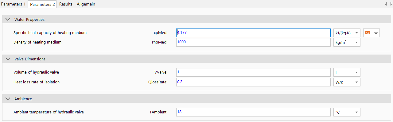
The parameters for the internal control valve (cpWater, rhoWater, VValve, QlossRate and TAmbient) must also be set. A detailed description of the parameters can be found in the HydraulicValveFlow component documentation.
Simple
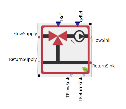
Basically, this simplified variant is the same as the basic variant, except that the grid connector is removed when UsePowerCalcPump is set to false.
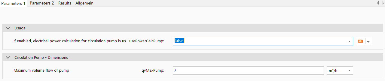
In this case only the maximum volume flow qvMaxPump of the pump must be set accordingly.
Examples
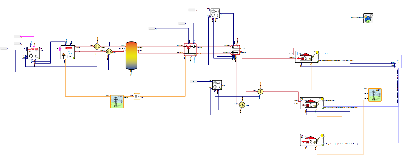
This image shows an example of how a HeatingUnitFlowTemperature can be integrated.