HeatPump
Symbol | 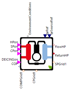 |
|---|
Use
Heat pumps are devices that transfer thermal energy from a source to a sink that is at a higher temperature than the source. To provide the usable thermal energy at a higher temperature they use electrical energy which is converted into mechanical work (mostly by compressors). For industrial applications environmental heat sources with high energy density are most commonly used (e.g. groundwater, river water, ground) and for home applications commonly the air.
Recommendation: This model is a more expert oriented and specific heat pump model with an internal simulation of the heat source and internal pumps (circulation and source), use the other heat pump for a better usability.
The HeatPump covers the following applications:
Basic: HeatPump for use in occupied buildings using the air as a heat source and without additional heaters
Auxiliary Heater: HeatPump is enabled to use internal electrical heating components through parameterization
Ground Heat Source: Switching the heat source of the HeatPump from air to the ground (Ground Collector)
3 Phase Electrical Connection: HeatPump is connected to a 3-phase mains supply (ac)
Parameters and Connectors
Basic
The HeatPump uses the switch-on and switch-off signals of the heat pump ▶HPon, the circulation pump ▶CPon, the source pump ▶SPon and the de-icing ▶DEICINGon as connectors. In addition, the reference volume flows for the circulation pump ▶qvRef and the source pump ▶qvSourceRef are specified externally. All the connectors mentioned above in this section (▶HPon, ▶CPon, ▶SPon, ▶DEICINGon, ▶qvRef and ▶qvSourceRef) are specified by the heat pump controller. Note that air heat pump needs to be de-iced during the heating process to completely ensure their functionality. To determine the ambient conditions of the air on the heat source side, these conditions are transferred from the environment model to the HeatPump via the ▶EnvironmentConditions connector. The condenser of the heat pump is connected to the flow line of the fluid system via the ▶FlowHP connector and to the return line of the fluid system via the ▶ReturnHP connector and then the heat is transferred from the HeatPump to the fluid (heat sink side). Finally, the single-phase electrical connector of the compressor ▶COMPGrid1, the circulation pump ▶CPGrid1 and the source pump ▶SPGrid1 must each be connected to a connector of the dc grid or with a phase tap to an ac grid.

In addition to the connectors, the parameters of the HeatPump must also be set. This includes switching off auxiliary electrical heating components by setting the AuxHeat parameter to false. As a result, the heat pump cannot be loaded from external heating elements and the heat supplied to the condenser is only obtained by the Clausius-Rankine cycle.
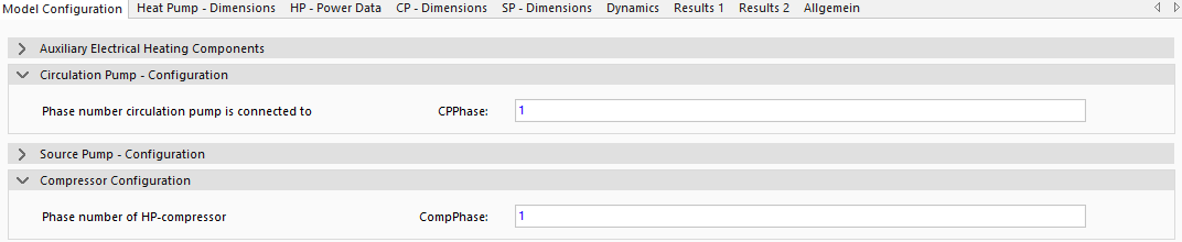
By setting the phase type for the circulation pump CPPhase and the compressor CompPhase, a distinction is made between ac and dc connections. For the CPPhase and CompPhase parameters, either the value 1 can be set for a dc connection or the value 3 for an ac connection.

When the air heat source is set for the HeatPump (SourceAir is true), the phase type for the source pump can also be selected with the SourcePhase parameter.
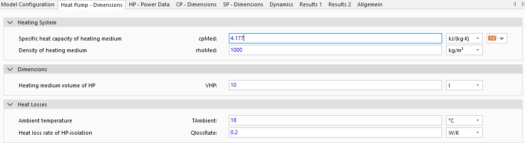
Under the Heating System group, the material values of the fluid (specific heat capacity cpMed and density rhoMed) of the medium on the heat sink side at the average typical operating temperature can be set. The volume of the fluid in the heat pump circuit VHP is used to calculate the thermal inertia and can be adjusted in proportion to the HeatPump capacity without knowing the exact value. To set the heat losses, a constant ambient temperature for the HeatPump TAmbient is assumed and the heat loss rate of the heat pump insulation is defined by the parameter QlossRate. The heat loss rate QlossRate is set by default for a typical industrial heat pump and can be further adjusted if required.
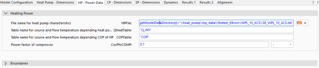
Due to heat pump system complexity, when compared to other heating systems such as condensing boilers or CHPs, the modeled system complexity had to be reduced to decrease simulation time. Heat power output highly depends on inner system states and working medium characteristics. To reduce model complexity inner system processes were neglected completely. Instead of simulating the inner processes, the heat power output is calculated using measurement data of heat pump system manufacturers HPFile. The heat power output QHeatTable and coefficient of performance COPTable of the heat pump system is thus characterized dependent on heating system sink flow temperature and heat source temperature (i.e. air, ground water, ground). This data is commonly available for most heat pump systems. Example data for a variety of heat pump systems is given in the model data directory (not visible in SimulationX). If further systems should be simulated, please use these data files as templates (path under HPFile) anf if no data is available for the used heat pump, use the provided default values. The power factor CosPhiCOMP is defined to calculate the effectively usable apparent power of the compressor.
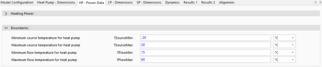
Note that minimum and maximum temperatures used to define the heat pump data must additionally be characterized in the group Boundaries. The parameters TSourceMin and TSourceMax must be set for the heat source side and TFlowMin and TFlowMax for the heat sink side. Use the technical information from the heat pump data sheet or the information from the technical drawing of the system.
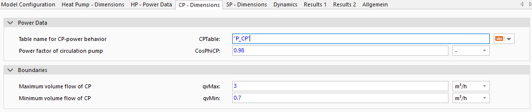
In the data of the HeatPump under the data file HPFile, the name of the parameter CPTable contains the power of the circulation pump as a function of the volume flow. In addition, the power factor CosPhiCP and the limit values of the volume flow qvMax and qvMin must be defined again. It should be noted that the HeatPump model has an integrated pump on the heat sink side, which transfers a volume flow to the :forward_arrow:FlowHP connector.
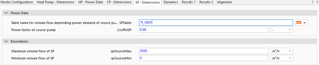
As a result of using the abstract approach from above the source pump does not realistically interact with the heat pump system. The source pump however has a non-neglectable electric power demand. The pump is thus modeled as a further electrical energy consumer. In the data of the HeatPump under the data file HPFile, the name of the parameter SPTable contains the power of the source pump as a function of the volume flow. In addition, the power factor CosPhiSP and the limit values of the volume flow qvSourceMax and qvSourceMin must be defined again. When parameterizing ambient air heat pumps focus must be given to the maximum and minimum source pump volume flows. Due to air heat pumps using a ventilator instead of a circulation pump, higher volume flows (e.g. 100 m3/h vs. 10 m3/h) might occur. It should thus be ensured that these parameters are defined accordingly to avoid incorrect system functionality. For parametrization reference is made to the heat pump source file in the data directory.
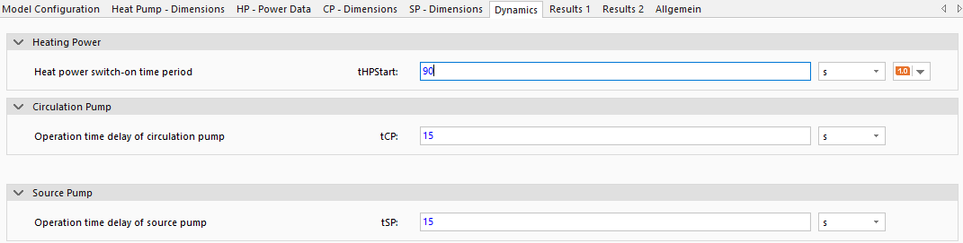
To simulate the behavior of the HeatPump, the model uses the typical start-up times during the start process for the heat pump tHPStart and the run-on times for the circulation pump tCP and the source pump tSP. The start-up time tHPStart defines how long the HeatPump must be switched on. The run-on times specify the times during which the pumps are still active after the heat pump is switched off.
Auxiliary Heater
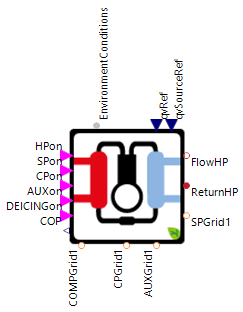

If the maximum heat generation of the heat pump (provision by the Clausius-Rankine cycle) is not sufficient to cover the system heat requirement, the heat generation can be increased via an additional heating component. To do this, the AuxHeat parameter must be set to true and the HeatPump is then equipped with an additional heating element. After setting AuxHeat to true, the AUXPhase parameter can be used to set the phase type of the newly appeared ▶AUXGrid1 connector (1 = dc, 3 = ac). The connector ▶AUXGrid1 must then also be connected directly to a dc grid or to an ac grid with a phase tap.

Under the HP - Power Data tab, a parameter AuxHeatPower now appears with which the constant auxiliary power of the heating element is defined.

The run-on times of the auxiliary heating component tAUX must then be set under the Dynamics tab so that the correct run-on behavior can be simulated.
Ground Heat Source
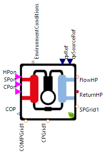

If ground water, well water or the ground is used as an environmental heat source the depth of ground depthGround from which the energy is taken must be defined in the associated parameter dialog HP - Power Data. Using the parameter depthGround and the season, an internal ground model calculates the heat source temperature based on the ground model. In case of modeling soil sensors, use an average ground depth depthGround as an input parameter.
3 Phase Electrical Connection
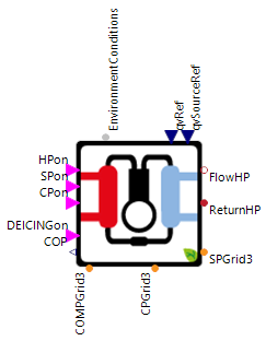
If the individual components of the heat pump have an ac connection, the number of phases for the individual components (CPPhase, COMPPhase and SourcePhase) can be changed to 3, i.e. ac, in the Model Configuration tab.
Examples
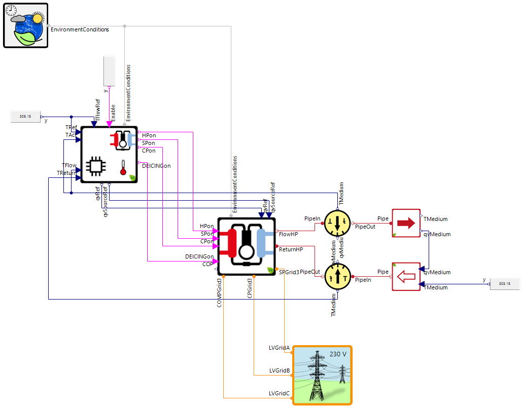
The image above shows a highly simplified example of the use of the HeatPump, which is intended to demonstrate the connection of the components via the connectors. The example shows the integration of the controlled HeatPump into a heat sink (e.g. a house) assuming a constant return temperature.
Model Background
Time Delays
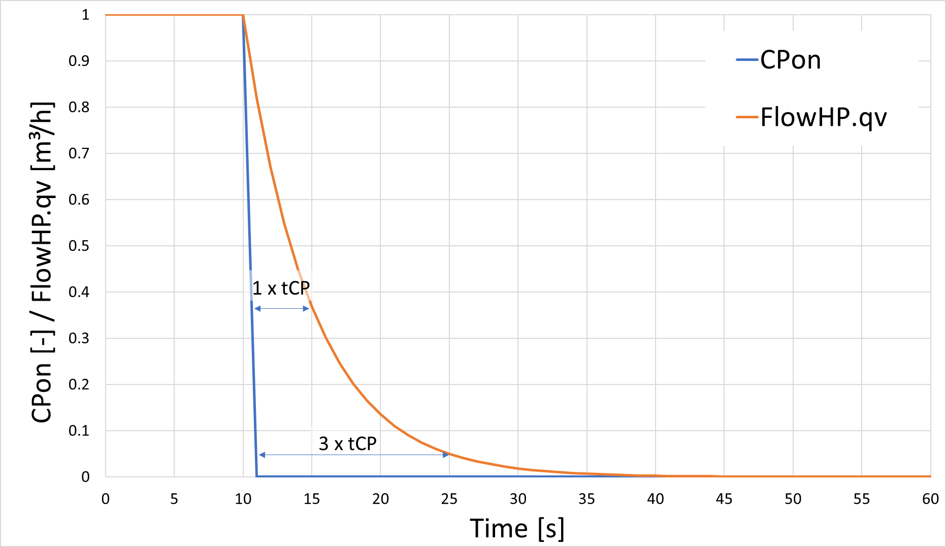
The times of the pumps and the HeatPump are modeled in the model via PT1 elements, whereby the entered parameters (e.g. tCP and tSP) represent the time constant of the PT1 element. When the HeatPump is switched off, the volume flows of the pumps qvRef and qvSourceRef decrease according to the typical behavior of the step response of a PT1 element. This means that after once the time constant (e.g. tCP= 5s) the volume flow drops to 37% of its original value, after twice the time constant (2 * tCP) to a value of 5% and after five times the time constant (5 * tCP) to 0.8%.
De-Icing
During the de-icing the devices are switched-off and the operation mode is reversed resulting in a heat transfer, so that the ice is melted. In the simulation the heat sink side (▶FlowHP and ▶ReturnHP) have the same temperature and electrical energy is consumed by the HeatPump.