Photovoltaics
Symbol |  |
|---|
Use
This model represents a scalable photovoltaic model. Photovoltaic systems use solar radiation as an environmental energy source to produce electrical energy. In this process they act as a DC-voltage source. To feed the local grid with renewable energy produced by a photovoltaic system a conversion from DC-voltage into AC-voltage, is necessary. Therefore, a PV-converter system is provided within the library.
Recommendation: Use the photovoltaics power plant if you only want to set the basic parameters or the newer version of this model under local.
Parameters and Connectors
To use the photovoltaics, the ▶EnvironmentConditions must be connected to the environment model and the ▶DC connector must be connected to the converter.
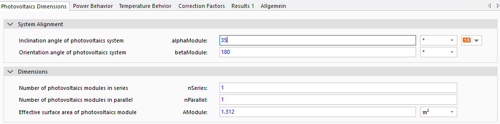
The basic parameters of photovoltaics can be found under the tab Photovoltaics Dimensions. These are the inclination angle alphaModule, the orientation angle betaModule, the number of photovoltaic modules in series nSeries, in parallel nParallel, and the area of a photovoltaic module AModule.
Typical values for orientation and inclination angle are:
Inclination alphaModule
90° vertical
0° lying flat
Orientation betaModule
0° North
90° East
180° South
270° West
Note that modules connected in series increase the overall system voltage. Modules connected in parallel, on the other hand, increase current output of the PV system. The model itself calculates the system states for a single module and scales the results according to the defined system configuration.
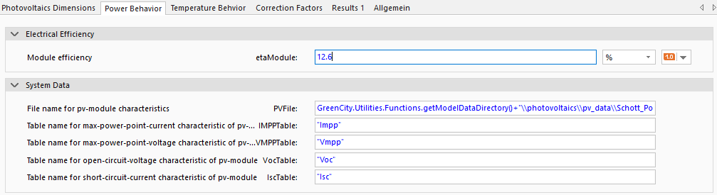
To calculate the module power, the efficiency of the module etaModule and the data of the PV module PVFile ( not visible in SimulationX) are required. The file with the module data PVFile contains the curves for the maximum power point (MPP) calculation IMPPTable and VMPPTable, as well as the open-circuit voltage curve VocTable and the short-circuit current curve IscTable depending on the solar radiation into module plane in W. This data is used to calculate the power of the PV module. If the data provided in GreenCity/Data/ModelData/photovoltaics/pv_data does not contain similar data to the module being modeled, these files can be used as a template for creating your own PV data.
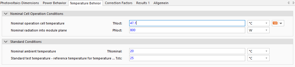
To determine the module temperature of the photovoltaic module, refer to the data sheet for the nominal operating cell temperature TNoct and the nominal solar radiation into module plane PNoct (for more information). Furthermore, the standard conditions for the ambient temperature TNominal and the standard test temperature Tstc are specified. Unless otherwise known, these values should be left at their standard values.
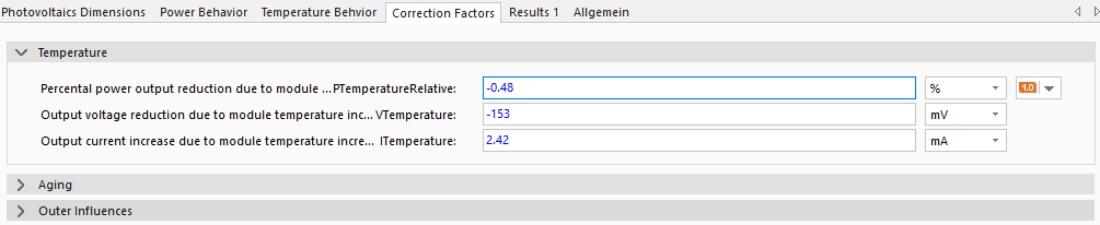
Based on the module temperature, the effects of temperature on the power PTemperatureRelative, the module voltage VTemperature, and the module current ITemperature are calculated. A negative value for these parameters (e.g., power PTempreatureRelative = -0.48%) means that the corresponding parameter decreases by this value per Kelvin (example: per K from TModule to Tstc, the power of the module decreases by 0.48%). For positive values, the corresponding parameter increases as the module temperature TModule rises. In general, module-temperature-specific power and voltage decrease and current increase (cf. temperature-specific behavior of semiconductor materials).
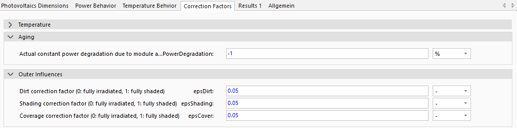
Additional effects on electrical power reduction such as module aging, can also be simulated. Concretely for this, the percentage PowerDegradation parameter must be specified. Normally, power degradation amounts about 1% a year (PowerDegradation should thus be set to -1%). Ensure that all algebraic signs are set correctly.
Influences of additional shading by surrounding objects (e.g. buildings, trees etc.) epsShading, dirt epdDirt and snow epsCover, can be considered statistically. These factors thus stay constant over the whole simulation time period. For annual simulations, special conditions like snow lying on the collector should be defined with an appropriate correction factor. As an example, if there is snow present for 1 day a year on the collector the corresponding correction factor epsSnow should be set to 1/365.
Model Background
Photovoltaics Module Temperature
Different photovoltaic module temperatures can cause differing system behavior. Therefore, a module temperature simulation is necessary. Note that a dynamic collector temperature simulation is not conducted as to reduce simulation time. Instead, standard data sheet values (NOCT - Normal Operating Cell Temperature) are used in the model for module temperature calculation:
Photovoltaics Electrical Behavior
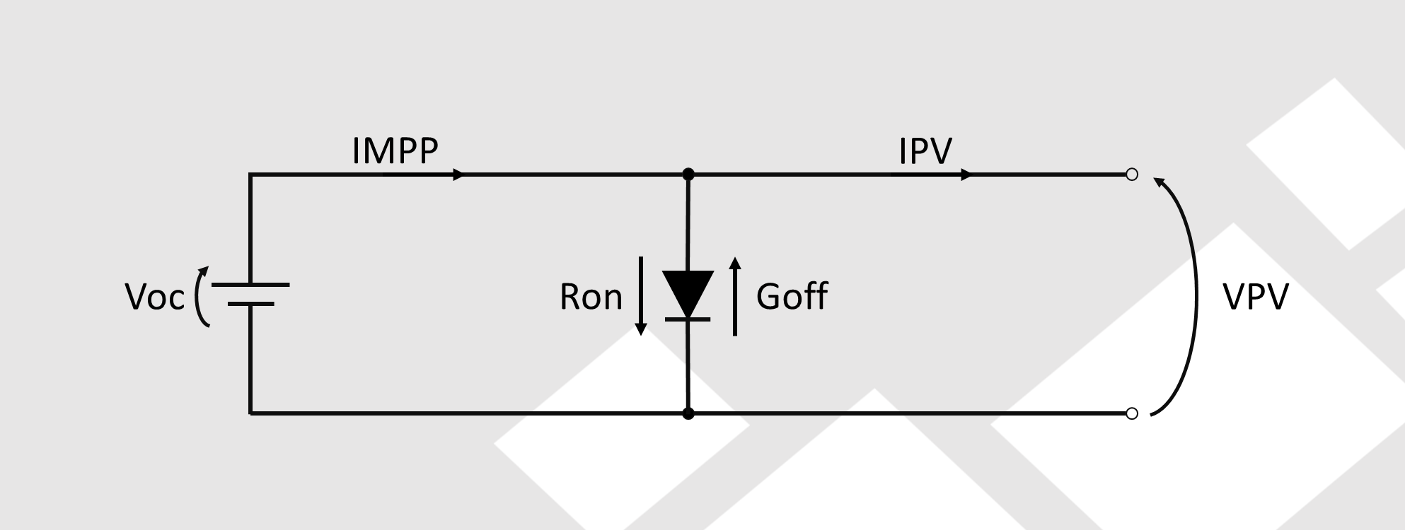
To simulate the electrical behavior of a PV system, a 1-diode-model is implemented. This model enables the simulation of the characteristic voltage and current behavior of a PV module dependent on solar radiation. Here, the forward resistance Ron and backward conductance Goff are calculated internally: