RadiantLoop
Symbol | 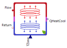 |
|---|
Use
Radiant loops are combined heating and cooling surfaces mainly in floor or ceiling which can either provide heating or cooling power to a room or the complete building. The main model task is to calculate the supplied heating an cooling power dependent on current flow temperature, return temperature and hydronic volume flow. Furthermore, an additional model output is the corresponding return temperature of the hydronic system dependent on the parameterized heating/cooling transmission values and internal thermal inertia.
The RadiantLoop covers the following applications:
Basic: RadiantLoop for floor systems which are designed based on the heating power
Panel Design With Heating Power: Panel design is done by the cooling power
Ceiling Panels: RadiantLoop are mounted on the ceiling
Parameters and Connectors
Basic
The RadiantPanels has the following connectors the heat medium inlet ▶Flow, the heat medium outlet ▶Return, and the target temperature of the room ▶TZone. In addition, the heating or cooling capacity of the RadiantPanel ▶QHeatCool is also output as a connector.
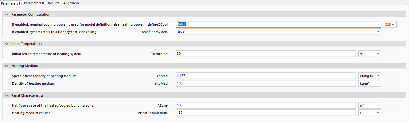
The parameter defineQCool determines the layout of the panels based on the nominal heating capacity (defineQCool is false). This depends on the available data for the RadiantPanels. The panels can be mounted either on the floor (useAsFloorSystem is true) or on the ceiling (useAsFloorSystem is false). The calculation of heat transfer changes accordingly.
To ensure numerical stability during initialization, the initial return temperature should be set to TReturnInit at this point in time in accordance with the expected temperature at this point in time. In most cases, the default setting of 30°C is sufficient.
The heat transfer medium of RadiantPanels is determined by the specific heat capacity cpMed and density rhoMed of the heat transfer medium.
Additional parameters for calibrating the models can be found in the data sheet, including the net floor area of the room zone AZone and the volume of the heat transfer medium within the RadiantLoop VHeatCoolMedium.
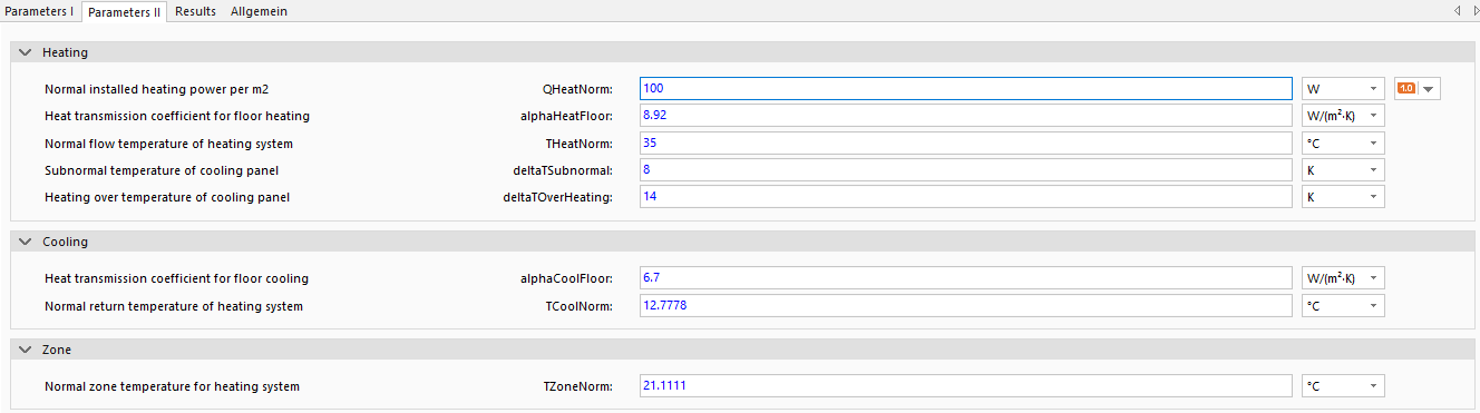
The nominal heating capacity QHeatNorm, the nominal heat transfer in heating mode alphaHeatFloor, the nominal temperature in cooling mode THeatNorm and the maximum subcooling of the cooling panel deltaTSubnormal, and maximum superheating of the cooling panel deltaTOverHeating from the data sheet are required for the design. The subcooling and superheating of the panels ensure that the design is adjusted to the heat output of the exact configuration of the RadiantPanels.
The floor panels cooling is physically determined using a heat transfer coefficient for cooling alphaCoolFloor and the nominal temperature of the system in heating mode TCoolNorm.
To determine the heat transfer, an approximate temperature TZoneNorm for the room to be heated or cooled must be specified. This temperature is normally between 20-23°C. A more detailed overview of how to calculate the heat output can be found here.
Panel Design With Cooling Power

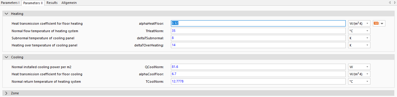
If the ceiling panels are designed based on heat output (defineQCool is true), the parameters for heating must be set nevertheless. These parameters are heat transfer coefficient alphaHeatFloor, nominal temperature THeatNorm, maximum subcooling of the cooling panel deltaTSubnormal, and maximum superheating of the cooling panel deltaTOverHeating.
The design of the RadiantLoop is based on the cooling power and the parameters the installed cooling power per
Ceiling Panels

If the panel is to be mounted on the ceiling (parameter useAsFloorSystem is true), the heat transfer coefficients for cooling and heating within the model change.
Model Background
Heating and Cooling Power Calculation
Concretely, the current heating or cooling power is calculated using the systems current medium temperature TWater, current room temperature TRoom, partial heat transmission coefficients kappa and corresponding heat transfer coefficient alphaHeat or alphaCool.
The partial heat transmission coefficient kappa represents nominal heating or cooling power of a modeled hydronic heat transfer system including the thermal inertia of the surrounding surface (i.e. floor, ceiling, panel). It is internally calculated in the model by considering nominal heating or cooling power (according availability - defineCool) and nominal temperatures (e.g. nominal flow temperature of floor heating system is about 35 °C, nominal room temperature is about 21 °C).
The corresponding heat transfer coefficient alpha represents heat transfer between the heated surface and the room itself. For heated ceilings and cooled floors it is constant at a value of 6.7 W/(m2K). For heated floors and cooled ceiling on the other hand, the following basic characteristic of floor heating systems is used to calculate this value:
Here, nominal temperatures either for cooling or heating are inserted in this equation to calculate the corresponding temperature difference which in turn is dependent on the nominal heating or cooling power output.
The radiant loop model is parameterized using the size of the affected area (i.e. heated zone surface area) and the nominal heating or cooling power. The heating and cooling power of individual systems are often co-dependent as per system design and characteristics. The individual powers of each system are not always available or calculable. Due to this the following equation is used for calculation: