VentilationSystem
Symbol | 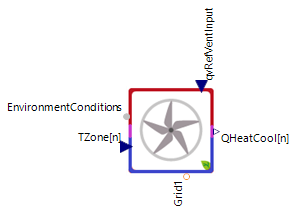 |
|---|
Use
The VentilationSystem models supply and exhaust ventilation for up to five building zones, including heating, cooling and fan electrical demand. The air flows are distributed according to fixed zone shares. External devices can provide additional heating or cooling of the supply air.
This model should be used together with the FanController or the VolumeFlowController. Use the FanController when the airflow should be adjusted directly according to the difference between the actual zone temperature and its target temperature. Use the VolumeFlowController when the flow calculation should also account for heating or cooling capacity and flow and return temperatures.
The controller output ▶qvRef supplies the reference airflow for the enabled fans. Supply and exhaust commands can be controlled independently.
The VentilationSystem covers the following applications:
Basic: The enabled fans supply fresh air or extract zone air according to external airflow commands
Output Controlled Air Flow: VentilationSystem uses only an exhaust fan
Heat Recovery: Supply and exhaust ventilation recover heat or cold from the exchanged air
Precooling: Allows Precooling of the supply air
Preheating: Allows Preheating of the supply air
3 Phase Electrical Connection: Use a three-phase grid connector instead of a single-phase connector
Parameters and Connectors
Basic
The connector ▶EnvironmentConditions provides the outdoor temperature and air properties. Connect the actual zone temperatures to ▶TZone[n] and the total supply airflow command to ▶qvRefVentInput. The output ▶QHeatCool[n] provides each zone's thermal power. The fan receives its electrical supply through ▶Grid1.
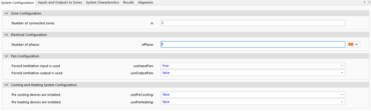
The parameter n defines the number of connected zones and the size of the zone vectors. It must be between one and five. The switches useInputFan and useOutputFan enable the supply and exhaust fans, respectively. For basic supply ventilation, set useInputFan to true and useOutputFan to false. At least one fan must be enabled. The parameter nPhase selects the number of electrical phases and is set to one for a single-phase connection (set nPhase to one or three).

The parameters InputRate1, InputRate2, InputRate3, InputRate4 and InputRate5 define the fraction of the total supply flow delivered to each corresponding zone (Number of parameters depends on n) and their sum must be one. By default, the first zone receives the complete flow.
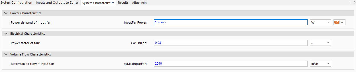
The parameter inputFanPower defines the electrical demand at the nominal maximum airflow qvMaxInputFan (data can be used from the fan datasheet) and scales electrical demand dependent on the air volume flow. The power factor CosPhiFan determines the reactive power demand of the enabled fans.
Output Controlled Air Flow
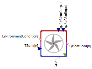

Enabling useOutputFan adds ▶qvRefVentOutput for the definition of the total exhaust airflow. If useInputFan is disabled, the supply airflow input is removed and the system operates with exhaust only.
The parameters OutputRate1, OutputRate2, OutputRate3, OutputRate4 and OutputRate5 of the tab 'Inputs and Outputs to Zone' define the exhaust fraction of each zone and follow the same availability and sum requirements as the supply shares. The parameter outputFanPower defines the exhaust fan demand at its nominal maximum airflow qvMaxOutputFan.
Heat Recovery
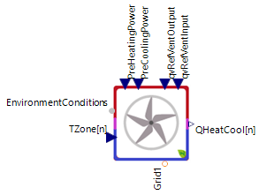

Enable both fans to make both airflow inputs available (useInputFan and useOutputFan are true) and allow a heat recovery between the zones and exhaust air.
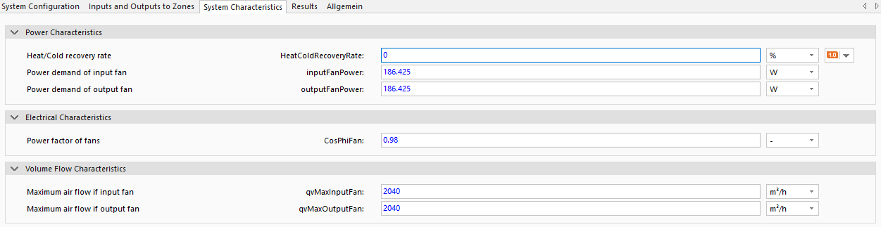
The parameter HeatColdRecoveryRate defines the recovered fraction of the temperature difference between zone air and outdoor air. It affects the exhaust temperature and the thermal power of the matched supply and exhaust flow in each zone.
Precooling
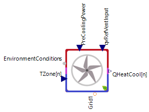
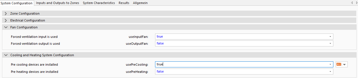
With the supply fan enabled, set usePreCooling to true to add ▶PreCoolingPower. This input specifies the total cooling power provided by an external device (use negative values). The model distributes the cooling power according to the supply shares and adds it to each zone's thermal output.
Preheating
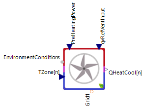
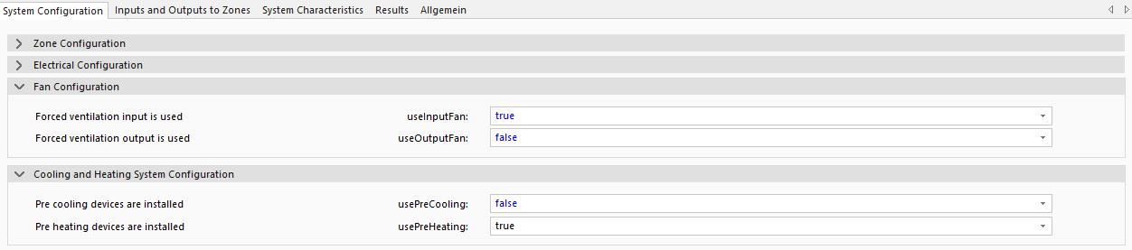
With the supply fan enabled, set usePreHeating to true to add ▶PreHeatingPower. This input specifies the total heating power provided by an external device (use positive values). The model distributes the heating power according to the supply shares and adds it to each zone's thermal output. Preheating and precooling can be enabled together, with or without heat recovery.
3 Phase Electrical Connection
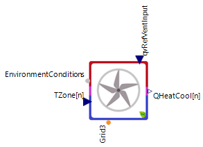

If the fans use a three-phase mains supply, change nPhase to three in the System Configuration tab. The electrical connector changes from the single-phase connector to ▶Grid3. The active and reactive fan power is divided equally across the three phases.
Model Background
The heating or cooling power is calculated separately for each zone from leakage air exchange, the matched supply and exhaust flow, and the external conditioning powers:
Here,
The exhaust air temperature used in the zone calculation is:
The internal RecoveryRate equals the recovery parameter when both fans are enabled and is otherwise zero.
The total electrical demand PowerOutput is the sum of the power required by the enabled supply and exhaust fans.