SolarThermal
Symbol | 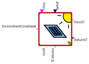 |
|---|
Use
This model represents a scalable solar thermal collector. Solar thermal collectors use solar radiation as an environmental energy source to produce thermal energy (heat). Heat supply is controlled by an external controller which controls volume flow output of the solar thermal circulation pump dependent on temperature spread between heat sink (mostly solar thermal storage) and collector temperature.
Recommendation: Use the newer version of this model under local.
The SolarThermal covers the following applications:
Basic: One phase connection (dc) to the grid
3 Phase Connection: Three Phase connection (ac) to the grid
Parameters and Connectors
Basic
The solar thermal has to be connected with the Environment model via the ▶EnvironmentConditions to get the information about radiation and ambient temperature. The collected heat energy can be transferred and used via the ▶FlowST and ▶ReturnST connectors. For the connection to the dc grid or the ac grid via a phase tap, use the connector ▶Grid1. The target values for the activation of the circulation pump ▶CPon and the volume flow ▶qvRef should be connected to the corresponding controller.
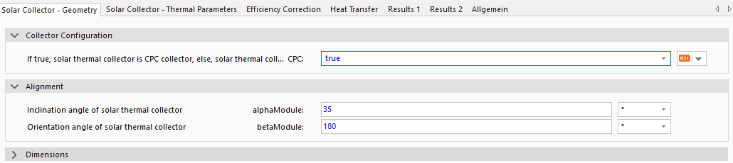
It must be set whether it is an CPC collector (CPC is true) or flat plate collector (CPC is false). The solar thermal system to be modeled should be configured using the parameter dialog. Here, the system inclination (alphaModule - 90° vertical, 0° lying flat) and orientation angle (betaModule - 0° North, 90° East, 180° South, 270° West) must be defined.
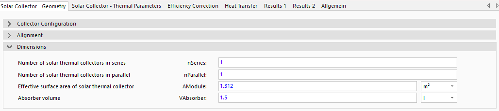
The number of connected collectors (nSeries and nParallel) and the collector surface area (AModule) and liquid volume (VAbsorber) per module must also be parameterized. Note that an increased number of collectors connected in series increases collector flow temperature. Several collectors connected in parallel increase the volume flow output.

Further details must be transferred from the data sheet of the collector to the parameter dialogue, such as optimal efficiencs of the solar thermal collector etaOptical, the linear heat transmission coefficient a1 and quadratic heat transmission coefficient a2.
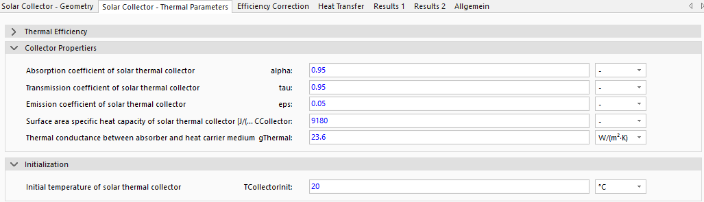
The parameters absorption coefficient alpha, transmission coefficient tau and emission coefficient eps must also be overwritten. Parameters surface area specific heat capacity CCollector and thermal conductance between absorber and collector gThermal are different. They can't be extracted from the data sheet of the solar collecotr und must be collected from measurement data. This two values should be set at the pre-defined values, if information is not available. The initial collector temperature (TCollectorInit) must also be set.

Influences of additional shading by surrounding objects (e.g. buildings, trees etc.) epsShading, dirt epdDirt and snow epsCover, can be considered statistically. These factors thus stay constant over the whole simulation time period. For annual simulations, special conditions like snow lying on the collector should be defined with an appropriate correction factor. As an example, if there is snow present for 1 day a year on the collector the corresponding correction factor epsSnow should be set to 1/365.

To determine the behavior of the heat carrier medium, its material properties must be entered (specific heat capacity cpMed and density of the medium at the typical operating point rhoMed). The default values are for a mixture of water and glycol (38% glycol-water mixture), which is most commonly used.
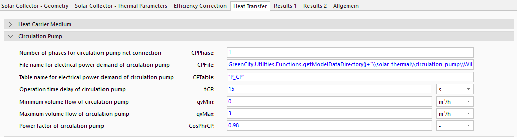
The basic configuration uses a single-phase connection (dc) for the circulation pump (CPPhase is 1). For the circulation pump, the power of the circulation pump in W as a function of the volume flow must also be defined in the GreenCity/Data/ModelData/condensing_boiler/circulation_pump folder (not visible in SimulationX) CPFile under the CPTable table or use an existing file. The time constant for the circulation pumps response to the solar thermal system starting or shutting down must be defined tCP. The power factor of the pump must be set using the parameter CosPhiCP and the technically possible volumes are then limited by the maximum volume flow qvMax and the minimum volume flow qvMin.
3 Phase Connection
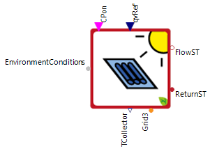

When setting the parameter CPPhase to 3, the connector ▶Grid3 becomes available and can be directly connected to the ac grid.
Model Background
Heat Capacity of the Collector
The model itself calculates system states related to 1m2 collector surface area and scales these results to the defined system configuration. That is why the specific heat capacity of the collector must be parameterized with surface-area-specific heat capacity ([CCollector=J/(m2*K)). Note that in the parameter tap Solar Collector - Thermal Parameters, no unit is given as this unit size is not available in Modelica. This combined SI-unit parameter CCollector is normally, available in the collector data sheets.
Temperature Calculation
Due to the high dependency between solar collector temperature and resulting heat power output, collector temperature behavior is modeled, combining a detailed differential-algebraic equation system and collector parameters from data sheets (must be defined within parameter dialog):
Incidence Angle Modifier
Besides constant module parameters which can easily be extracted from collector module data sheets, the Incidence Angle Modifier (IAM) is a very important influencing value, which describes the system influences of non-vertical angles of incidence onto the collector plane. This factor is dependent on the angle of incidence in transversal and longitudinal direction and the collector design.
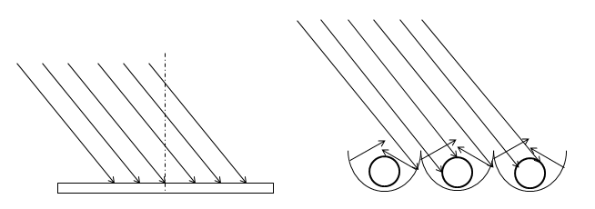
For flat plate collectors (left side in picture above) a reduction of the angle of incidence, related to the vertical, causes a decreased system efficiency (longitudinal and transversal). This is different for CPC collectors (Compound Parabolic Concentrator - right side in picture above). Due to their design, these types of collectors concentrate direct solar radiation. As a result, the overall system efficiency can even be increased for inclined solar radiation. If a CPC collector is to be modeled, the parameter 'CPC' should be set to 'true.' Internally, different efficiency characteristics are used for simulation.
Time Dynamics
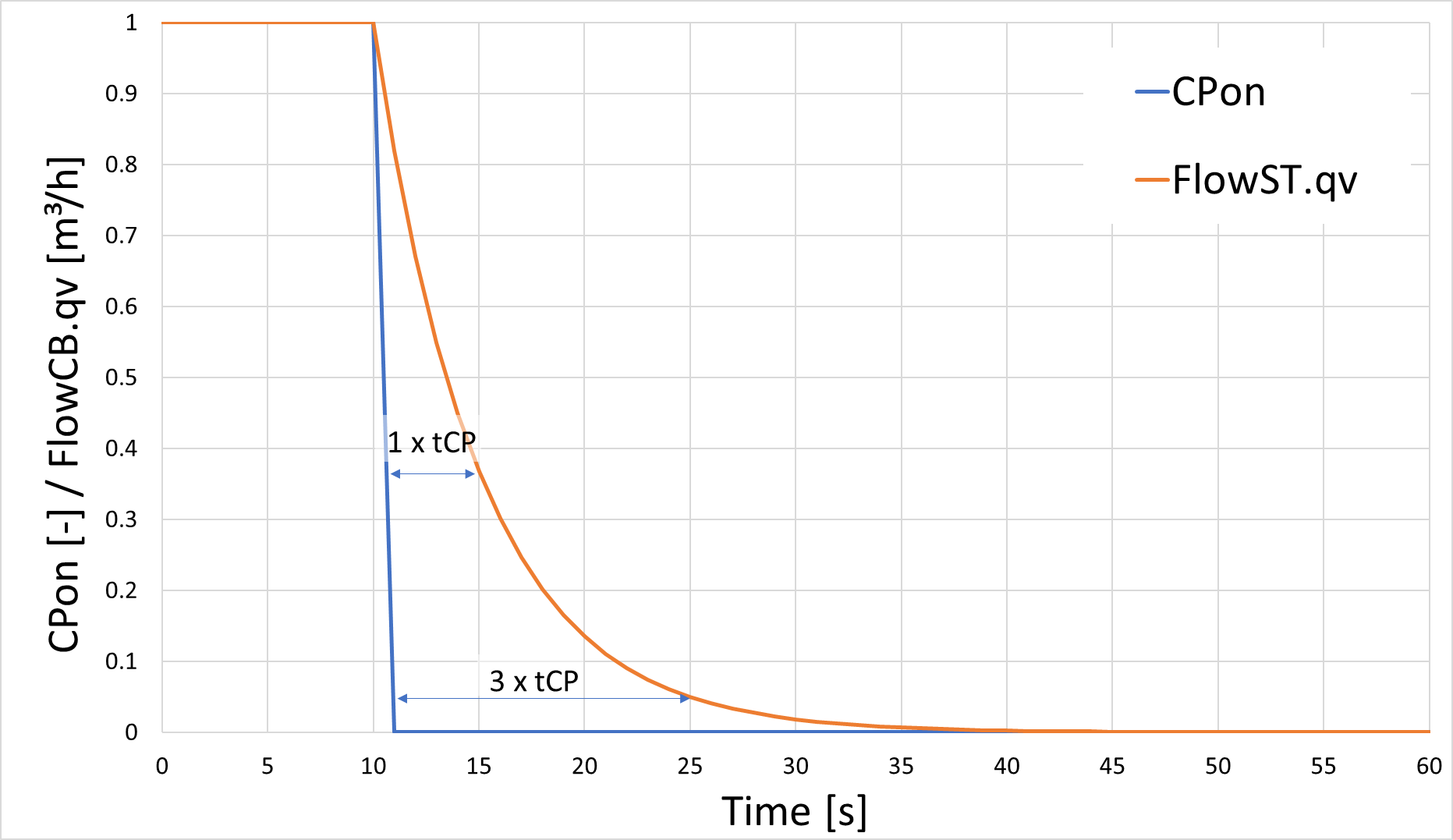
The times of the pumps and the CombinedHeatAndPowerUnit are modeled in the model via PT1 elements, whereby the entered parameter tCP represents the time constant of the PT1 element. When the CombinedHeatAndPowerUnit is switched on, the thermal power QSolarThermal increases according to the typical behavior of the step response of a PT1 element. This means that after once the time constant (e.g. tCP = 5s) the heating power QSolarThermal rises to 63% of its original value, after twice the time constant (2 * tCP) to a value of 95% and after five times the time constant (5 * tCP) to 99.2%.