PumpStoragePlant
Symbol |  |
|---|
Use
The pump storage plant is a form of a hydraulic power storage which uses the potential energy difference of water between two levels of height, to store and generate electrical energy. The water is pumped up from the bottom basin into the top basin in order to store it and, when required, the potential energy of the top basin is converted back into electrical energy via a turbine.
Parameters and Connectors
As connectors, the PumpStoragePlant requires a specified target power ▶PRef and a connection to the grid model of the corresponding voltage level (LV, MV, HV) ▶MVGrid. Note that positive power values for ▶PRef are an energy input into the storage and negative values represent the extraction from the storage. Furthermore, positive values for ▶PRef are ignored if the storage is already filled (SOC = SOCMax) and negative values are ignored in case of an empty storage (SOC = SOCMin).
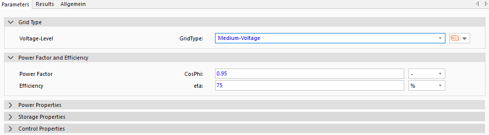
The Voltage-Level parameter is used to set the voltage level of the PumpStoragePlant. The possible settings are Low-Voltage (LV), Medium-Voltage (MV) or High-Voltage (HV). With the corresponding setting the connector ▶MVGrid changes. CosPhi sets the ratio of active power to apparent power and eta is the total efficiency of a whole charging and discharging cycle.
The maximum power of the PumpStoragePlant is defined by the height difference between the top basin and the bottom basin hDrop and the maximum volume flow of the water qvMax of the Power Properties group. The maximum volume flow rate limits the maximum power that can be generated or obtained with the PumpStoragePlant. can be generated or obtained.
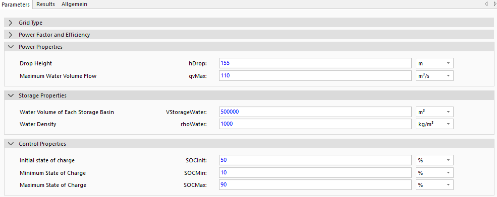
The parameters of the Storage Properties group are used to define the volumes per basin VStorageWater and the density of the water rhoWater. For PumpStoragePlant, it is assumed that there are only two basins, namely the top and the bottom basin. The last parameters listed in the figure are the Control Properties, which determine the SoC conditions of the PumpStoragePlant. SOCInit is the SoC of the storage at the beginning of the simulation, SOCMin is the minimum possible SoC and SOCMax is the maximum possible SoC of the PumpStoragePlant. For stable operation, the model includes an internal hysteresis of 5% for the SoCs SOCMin and SOCMax, i.e. when the storage tank has reached its maximum SoC SOCMax of 90%, it is no longer loaded until the SOC falls below 85%. The model behaves in the same way when the minimum SoC SOCMin is reached.
The storage energy content (ECharge and EDischarge) and state of charge (SOC) are calculated in each time step dependent on the transferred volume flow between the water basins.
Model Background
Water Supply And Water Losses
No change in the amount of water in the basins due to external influences is taken into account and it is also assumed that the evaporation of the water and the water supply to the basins are almost identical and therefore do not need to be taken into account. All conversion losses are integrated in the efficiency parameter eta.