PowerPlant
Symbol | 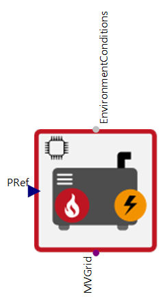 |
|---|
Use
PowerPlants are internal combustion engines that are used to generate electricity. The waste heat from the power plant is recooled via a cooling tower or similar system.
Parameters and Connectors
The model requires the connections ▶EnvironmentConditions to simulate the cooling power, the specification of the reference electricity production (▶PRef) and the connection to a power grid (default ▶MVGrid) to feed in the electricity produced. The PowerPlant was modelled with a Cogeneration in which the waste heat is not used for heating purposes but is dissipated via a dry cooler model.
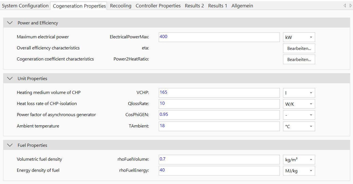
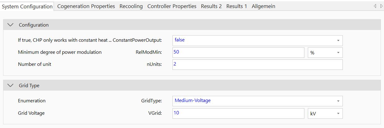
The ConstantOutput, RelModMon and nUnits settings can be set in the same way as for the CHP. This also applies to the entire CHP properties tab. The fuel used is usually biogas, natural gas, diesel or petrol (the fuel type is parameterised in the model via the rhoFuelVolume and rhoFuelEnergy parameters). The proportion of thermal energy is therefore the amount of energy that must be dissipated via the recooler. The GridType and VGrid parameters are taken from the grid model.
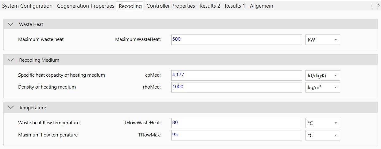
The parameters on the Recooling tab can be set in the same way as for the dry cooling tower. The only difference is that the maximum recooling power (MaximumWasteHeat) must also be defined. This is used for dimensioning the dry cooler.

The model contains an internal PowerController that is automatically adjusted based on the power plant parameterization. The SwitchOnPower parameter serves as the switch-on limit. If the requested electrical power ▶PRef exceeds or falls below this limit (taking the hysteresis PDiffCtrl into consideration), the controller turns the plant on or off, respectively.
Model Background
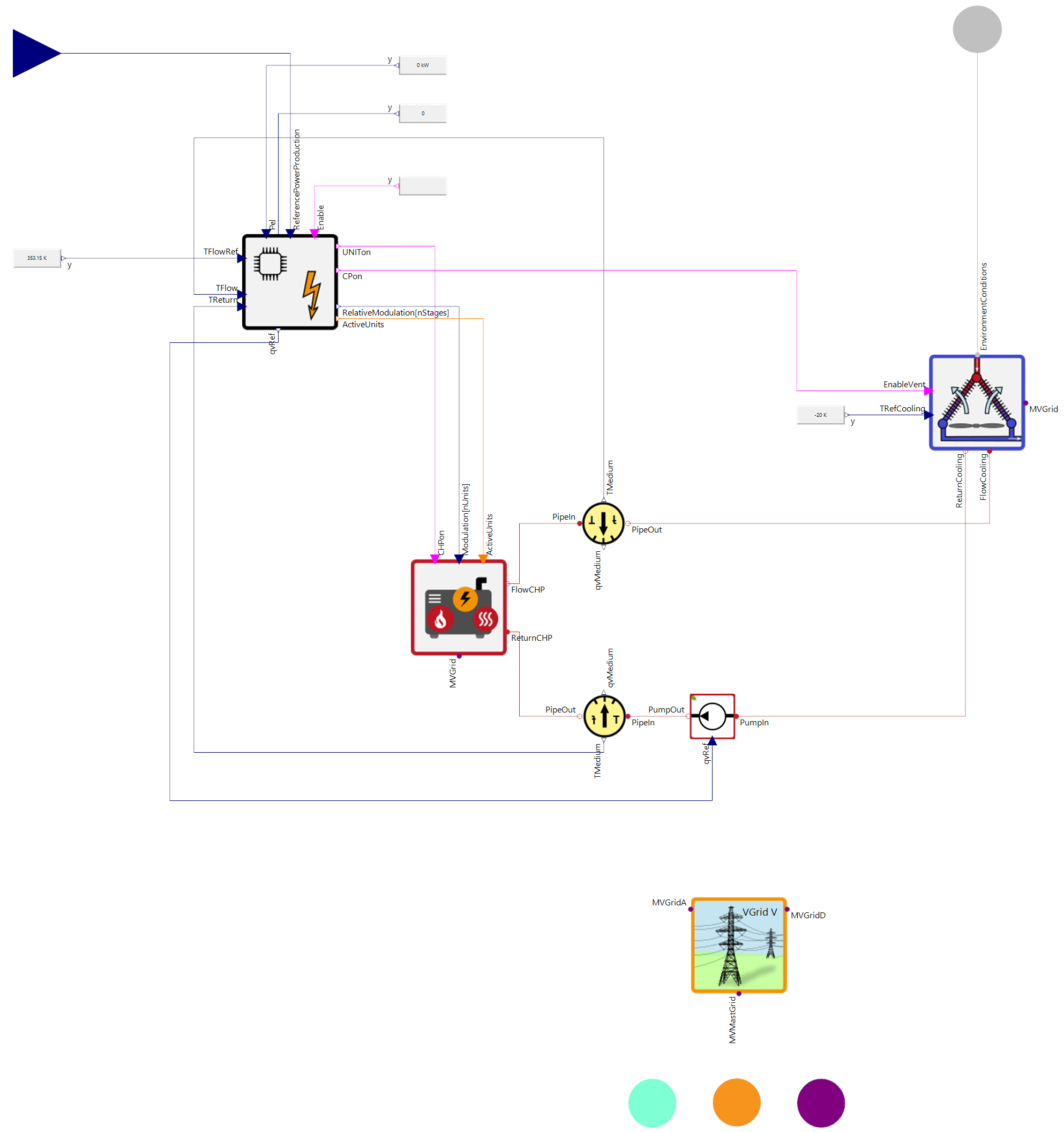
The internal structure of the model is shown in the following illustration.