BatteryCharger
Symbol | 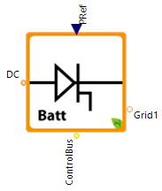 |
|---|
Use
The BatteryCharger is necessary to couple the DC-voltage storage with electric AC-voltage consumers or the AC-grid of a building. It combines the models of a DC converter, a DC control and a B6-converter or a B2-converter model.
Recommendation: This model is an older version of the ac battery inverter, only use this model due to legacy reasons.
The BatteryCharger covers the following applications:
Basic: The BatteryCharger converts the dc battery current to a 1-phase low voltage grid connection
1-Phase Grid Connection: The grid connection is changed to a 3-phase low voltage grid connection.
Parameters and Connectors
Basic
As connector, the BatteryCharger requires a specified target power ▶PRef where positive power values are an energy input into the storage and negative values represent the extraction from the storage. The reference charge (and discharge) power ▶PRef must be controlled by external controllers and is dependent on the inner building energy system or consumer states (e.g. renewable energy availability or simulated electricity prizes). Note that the reference charge and discharge power must be controlled by external controllers dependent on inner building energy system states (e.g. renewable energy availability).
The relevant battery parameters are transmitted from the battery via the ▶ControlBus connector. These parameters are the state of charge SoC and the minimum and maximum battery voltage. Furthermore, the battery is connected via the ▶DC connector and the dc Grid. To connect the BatteryCharger with the ac grid take a PhaseTap and define which phase of the 3-phase grid will be used.
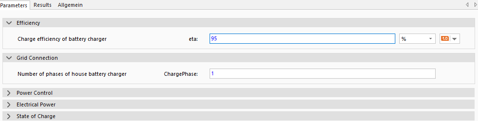
To set the grid parameters, the inverter efficiency of a charging and discharging cycle eta and the number of grid phases ChargePhase (either 1 phase or 3 phases) has to be set.
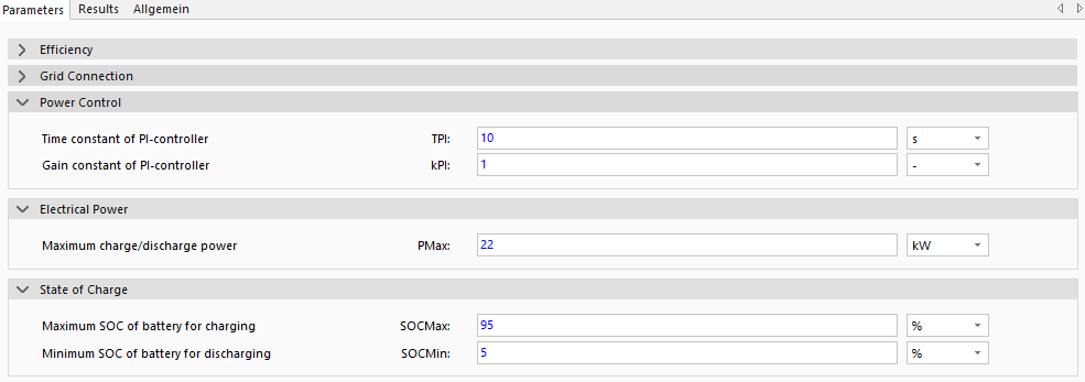
The parameters under the Power Control group contain the settings for the PI controller of the BatteryCharger TPI and kPI, which defines the behavior of the DC converter. The battery converter acts as a PI-controller which controls charge and discharge power via an intermediate-circuit voltage at the DC-side, dependent on the reference power ▶PRef. If no precise details are known for the PI controller of the BatteryCharger, the set standard parameters can be used.
Furthermore, the maximum charging/discharging power of the battery or the inverter on the BatteryCharger model is PMax, the maximum SoC up to which charging is to take place SOCMax and the minimum SoC up to which discharging is to take place SOCMin.
3-Phase Grid Connection
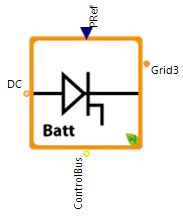
For the 3 phase grid connection the parameter ChargePhase gets changed to 3 to better model the connection of the BatteryCharger to the electrical grid.
Model Background
Reference Power Calculation
Positive values for ▶PRef are ignored if the storage is already filled (SOC = SOCMax) and negative values are ignored in case of an empty storage (SOC = SOCMin). For stable operation, the model includes an internal hysteresis of 5% for the SoCs SOCMin and SOCMax, i.e. when the storage tank has reached its maximum SoC SOCMax of 90%, it is no longer charged until the SOC falls below 85%. The model behaves in the same way when the minimum SoC SOCMin is reached.
Why Do I Get An Initialization Error?
Internally, the model either uses a B6- or B2-converter model. If the related maximum battery voltage exceeds a value of 0.9 times the effective grid voltage, the battery converter must be defined as a 3-phase converter. The maximum voltage of 3-phase converter is 2.34 times the effective grid voltage. Note that using a battery converter model as a single-phase converter, avoids high reactive power demands for voltage conversion.