StationaryBattery
Symbol |  |
|---|
Use
The StationaryBattery can be used to buffer peaks of renewable energy production and electricity demand in buildings or in combination with other electrical consumers. As batteries are DC-voltage storage systems they must be connected to the grid via battery or DC/AC converters. To use a complete battery model including the converter/inverter use the BatteryStorage.
The StationaryBattery is a highly dynamic battery cell impedance model including the following components:
Variable voltage source (dependent on SoC) representing the open-circuit-voltage
Internal ohmic resistance (dependent on cell temperature and SoC)
Constant-phase-elements (dependent on cell temperature and SoC) representing high and low internal resistance dynamics
Parameters and Connectors
The relevant battery parameters are transmitted from the battery via the ▶ControlBus connector. These parameters are mostly the state of charge SoC and the minimum and maximum battery voltage. Furthermore, the converter (e.g. ac converter) is connected via the ▶DC connector and allows the StationaryBattery to connect to the Grid.

When the ageing CalcAging is activated, the StationaryBattery takes into account thermal, state of charge-dependent and usage-dependent ageing effects via the Battery ageing model. Due to simulation time reduction being a pivotal characteristic for model usability, the battery is modeled as a free-parameterizable number of battery cells or modules. It is assumed that all cells or modules show the same behavior.
The user decides whether nominal battery parameters (useStandardParameter is true) or the number of parallel and serial battery cells nPar and nSer (useStandardParameter is false) should be used. If the nominal battery parameters are to be used, then the nominal battery voltage of a module VModuleNominal, the nominal total battery voltage VBattNominal, the nominal capacity of a module CModuleNominal and the total energy of the battery EMaxNominal must be defined. From these parameters, the model calculates the correct number of battery cell parameters (nSer and nPar) and uses these to calculate the temperature and current levels. For this conversion, the model uses standard battery cell parameters contained in the model data directory. The model can either model lithium-ion or lead-acid batteries using this standard data. If a special type of battery cell or module is to be simulated, additional battery data can be imported into the model data directory using the battery type data-file as a template.

The user can also parameterize cell specifications (i.e. number of cells or modules in series nSer and parallel nPar) manually using the parameter dialog (useStandardParameter is false) and the individual model parameters will than be taken from the battery type data-file.

To start in defined states, the initial state of the model is defined with regard to the ambient temperature TAmbient and the state of charge SOCInit. For the StationaryBattery it is assumed that the ambient temperature remains constant during the simulation.

To calculate the battery voltage, the resistance within the battery is calculated using a resistance model based on ZARC elements. As the first input parameter, the model requires the resistance of the connectors between the individual battery cells RTransfer. If no information is known for this parameter, the default value can be used. All other parameters are battery type specific and are saved under the specified path in the data folder (not visible under SimulationX) as ImpedanceFile. The charge state and temperature-dependent parameters of the resistance model are stored in this file and the parameters RsTable, R1Table, R2Table, CPET1Table, CPET2Table, CPEP1Table and CPEP2Table describe the individual components of this resistance model and their table name in the ImpedanceFile.

For further parameterization of the voltage, another file is stored in the data folder VocFile with the open-circuit voltage of the battery depending on the SOC and the name of the table in the file is defined via the parameter VocTable. In addition to the open-circuit voltage, the temperature-dependent change in the open-circuit voltage is included in the StationaryBattery via the alphaVoc factor. A value of 0.08 mV/K means that the open-circuit voltage increases by 0.08 mV at a battery temperature of 1K above 25°C, meaning at 26°C, and decreases by the same value at a temperature of 1K below 25°C. For the simulation the maximum and minimum voltage of the modeled battery cell or module (VMin and VMax) must also be declared. This is necessary to parameterize the battery converter model with the maximum and minimum permitted battery voltages. This ensures that the battery will not be over-charged or deep discharged during the simulation. Therefore, it is necessary to connect ▶ControlBus to the battery converter model to avoid numerical difficulties. For li-ion-cells the voltage range of 3.0V and 4.2V is normally used dependent on the open-circuit-voltage data. For lead-acid-battery modules this range is between 11.8V and 12.8V.

In order to model the temperature change of the battery, its heat capacity per cell/module CHeat and the thermal conductivity per cell/module gThermal must be specified. These parameters can be determined using complex measurements of the individual battery cells or, if no information on the exact battery type is known, the default values can be used. To avoid linear interpolation errors it is necessary to parameterize the minimum and maximum temperature (TMin und TMax) which are used to limit the temperature dependant battery behavior based on technical limitations of the battery.

To parameterize the capacity, another file is created in the data folder QRealFile with the relative change in capacity as a function of battery temperature and the name of the table in the file is defined via the parameters QMaxTable and QMinTable.

If the CalcAging parameter under the Model Initialization tab is true, the ageing of the battery is mapped via a separate ageing model and this data can be individually adjusted by selecting the ageing data. The standard values for lithium-ion batteries and lead-acid batteries are stored in the aging files in the AgingFile data folder. To define the table names in the ageing file, the lambdaTempTable, lambdaSOCTable and lambdaAhTable fields must be filled in.
Model Background
Electrical Battery Replacement Model
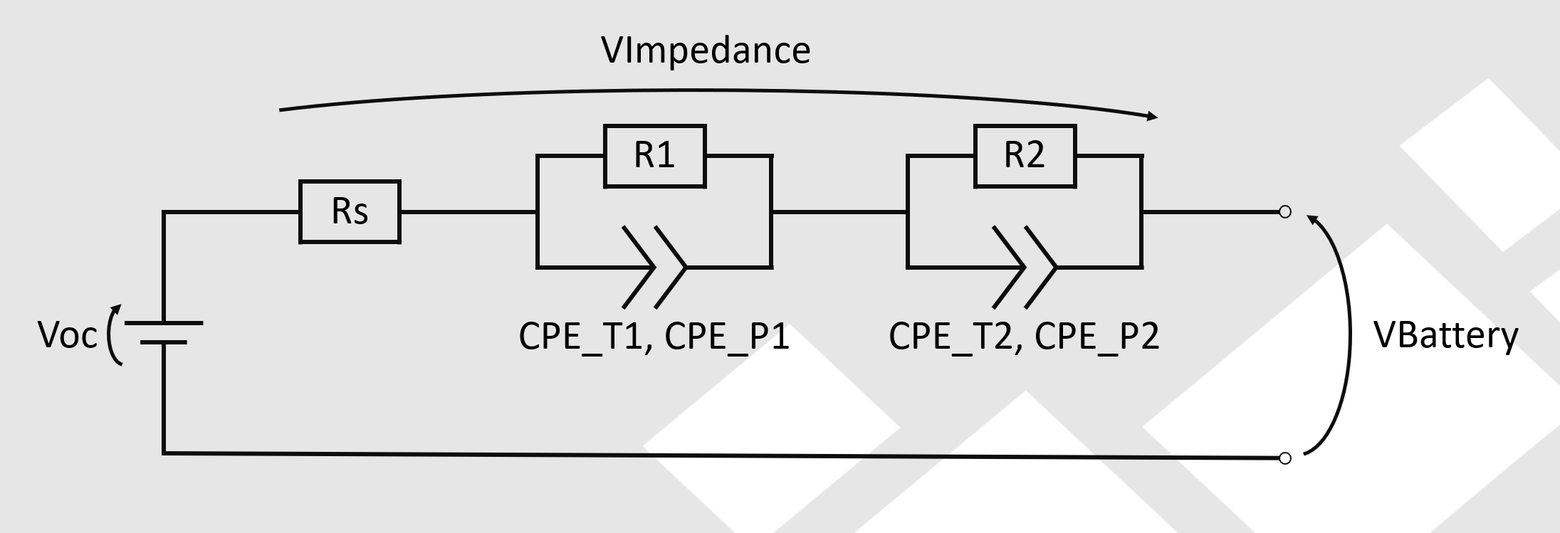
The figure above shows the electrical equivalent model for calculating the battery voltage without the transfer resistors RTransfer and is based on the series connection of an ohmic resistor and 2 ZARC elements, which consist of the parallel connection of an ohmic resistor and a constant phase element (CPE).
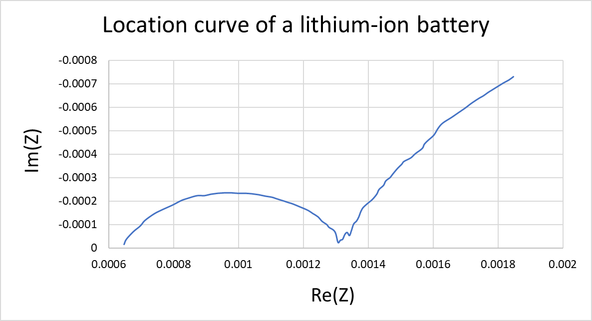
By using the Zarc elements, the complex impedance curve of a battery cell and thus the voltage curve can be simulated very accurately. The image above shows a complex impedance curve of a lithium-ion battery which can be simulated using the StationaryBattery for lithium-ion batteries.
SOH and SOF
The output of the battery aging simulation is internally converted to the SOH value (state of health) either dependent on cyclization or capacity. State of Health is always initialized with 100%. That way it is assumed that the simulated battery is new when the simulation begins. In general, a battery reaches its end of life when the SOH drops below 80%.
The State of function (SOF) is an additional simulation result which combines battery aging and actual temperature to a single value representing the actual usability of the simulated battery. Note that the temperature-specific capacity losses, in this process, are reversible.