CondensingBoilerStirling
Symbol | 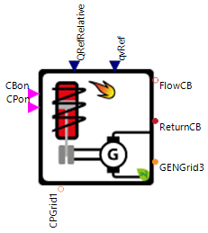 |
|---|
Use
Condensing boilers are central-heating boilers which convert, almost completely, the energy content of fuel into heat power output. The high system efficiency results from the usage of condensation (latent) energy of water vapor contained in the exhaust gas. Normally natural gas, oil or wood are used as fuels. This boiler model represents condensing boilers whose heat power outputs are modulated continuously (i.e. mainly gas-fired condensing boilers). Additionally, this model includes the functionality of an integrated Stirling-motor which is connected to an internal generator (confer combined heat and power unit). This motor provides the basis for the heat and electricity production of the model. When higher heat demands occur the condensing boiler module additionally switches on. The normal electrical power output of the Stirling motor is enough to meet basic electricity demands of a single-family house.
The CondensingBoilerStirling covers the following applications:
Basic: CondensingBoilerStirling without auxiliary heating systems and a 1-phase (dc) circulation pump
Auxiliary Heating: CondensingBoilerStirling is enabled to use internal electrical heating components through parameterization
3 Phase Connection: The circulation pump of the CondensingBoilerStirling has a 3-phase (ac) connection
Parameters and Connectors
Basic
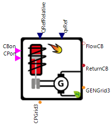
In the basic configuration the model has to be connected using the turn on/off signals for the boiler and the circulation pump (▶CBon and ▶CPon), the relative heat outtake compared to the maximum heat output at the current ambient flow temperature (▶QRefRelative), set point of the volume flow ▶qvRef, the intake and return pipes of the heat sink side (▶FlowCB and ▶ReturnCB), the ac grid connection for the electrical power outtake of the stirling cycle (▶GENGrid3) and the dc grid connection for the circulation pump consumption (▶CPGrid1). Most of the connectors should be set with the connectors of the continuous heat regulated controller or the electricity regulated controller for the boiler.
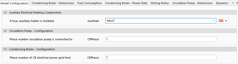
The basic configuration of the CondensingBoilerContinuous does not have an auxiliary heating system (AuxHeat is false) and uses a single-phase connection (dc) for the circulation pump (CPPhase is 1) and a three-phase connection (ac) for the power outtake of the stirling cycle (CBPhase is 3). After the model is configured all connectors should be available for connection to the ac grid directly or with a phase tap, to the boiler controller (e.g. heat or electricity regulated) and heating system (e.g. heat storage or consumers). Make sure that all connectors are characterized to avoid numerical difficulties.
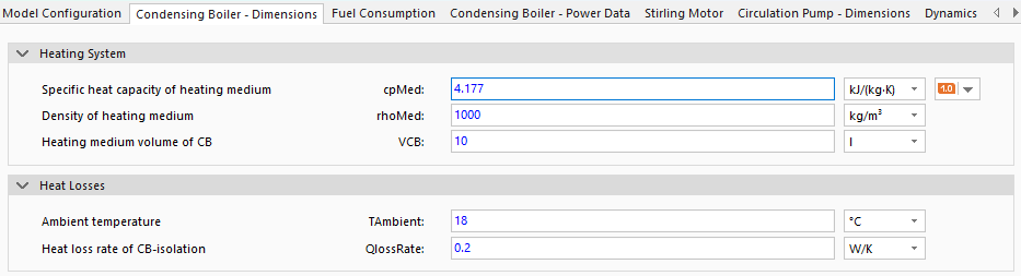
The material properties of the fluid in the heating system (specific heat capacity cpMed, density rhoMed, and volume of fluid in the boiler VCB) are used for dimensioning. Heat losses to the environment are determined using the parameters of the constant ambient temperature TAmbient and the heat loss rate through the boiler insulation QlossRate. The heat loss rate QlossRate is configured for a typical household boiler with good insulation and should be reduced for a boiler with better insulation and increased for poorer insulation. If the heat loss rate cannot be estimated, the default value should be used.

To determine the fuel consumption, the volumetric fuel density rhoFuelVolume and the energetic fuel density rhoFuelEnergy must be specified (default values for gasoline).
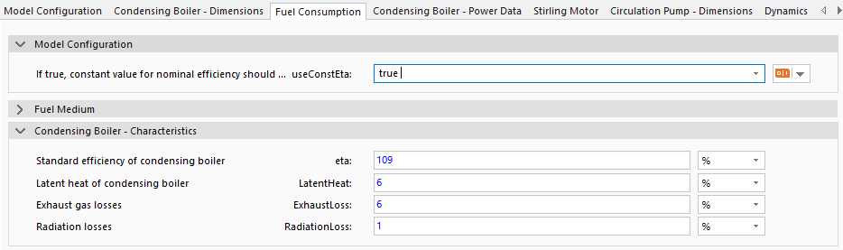
The efficiency calculation is the main component of this simulation model. The parameter useConstEta determines whether the nominal fuel efficiency of the boiler is constant (useConstEta is true) or is represented by the specific information in the data sheet (useConstEta is false).
For constant nominal fuel efficiency (useConstEta is true), this is specified via the parameter for efficiency relating to net calorific value eta. This efficiency eta is converted to the effective efficiency of the system
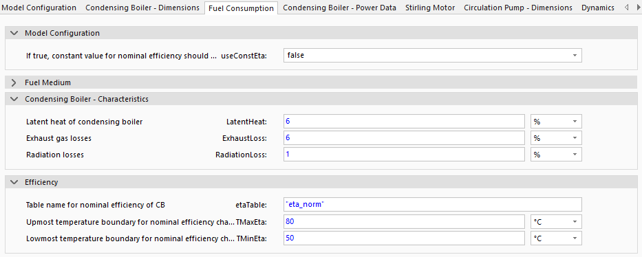
The other variant (useConstEta is false) uses a temperature-dependent efficiency relating to net calorific value etaTable, which is defined in the parameter file CBFile under Condensing Boiler - Power Data. etaTable is predefined in the ModelData directory for various boiler types and can be selected via the CBFile setting. If a custom condensing boiler system is to be modeled, the boiler data file in the model directory under GreenCity/Data/ModelData/condensing_boiler/CB_data (not visible in SimulationX) can be used as a template. To limit the technically possible temperatures, the maximum temperature limit TMaxEta and the minimum temperature limit TMinEta are also defined. If no exact figures are known for the boiler, then the constant approach should be chosen. Typical standard values and the calculation of boiler efficiency can be found in the section Fuel Utilization Efficiency.
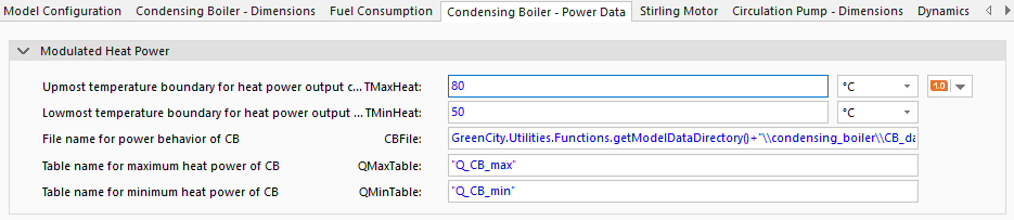
The definition of the heat outputs per burner stage depending on the flow temperature (T of ▶FlowCB) is defined in the file CBFile in the folder GreenCity/Data/ModelData/condensing_boiler/CB_data (not visible in SimulationX), and the heat outputs are specified using the tables QMaxTable and QMinTable. QMaxTable specifies the heat output of the boiler with both burner stages in W depending on the flow temperature in K, and QMinTable specifies the heat output with only the first burner stage. If other condensing boiler systems are to be modeled, use the condensing boiler data file in the model data directory as a template and adjust the values and file name accordingly. To limit the technically possible temperatures, the maximum temperature limit TMaxHeat and the minimum temperature limit TMinHeat are also defined.
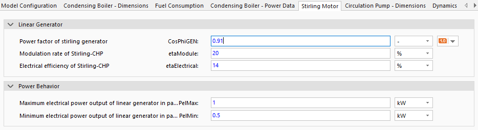
To set up the Stirling engine within the Stirling process, the power factor of the Stirling generator CosPhiGEN, the maximum percentage contribution of the Stirling generator to the heat input via the burners etaModule, and the conversion efficiency of the Stirling cycle from fuel to electrical energy etaElectrical are required. To further refine the data, the maximum and minimum electrical power of the Stirling cycle PelMax and PelMin must be entered.
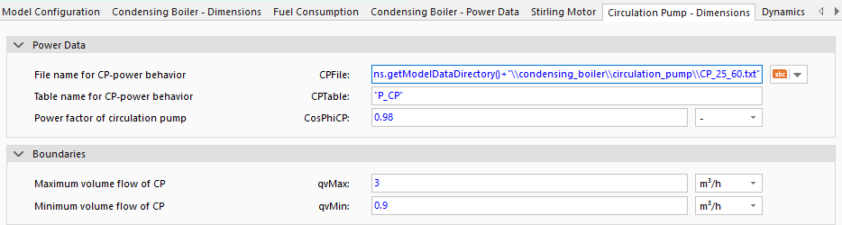
For the circulation pump, the power of the circulation pump in W as a function of the volume flow must also be defined in the GreenCity/Data/ModelData/condensing_boiler/circulation_pump folder (not visible in SimulationX) CPFile under the CPTable table. The power factor of the pump must be set using the parameter CosPhiCP, and the technically possible volumes are then limited by the maximum volume flow qvMax and the minimum volume flow qvMin.
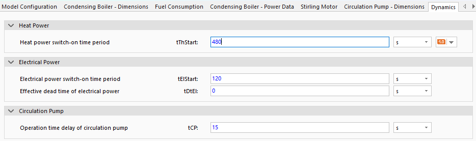
To simulate the behavior of the CondensingBoilerContinuous, the model uses the typical start-up times during the start process for the boiler tThStart and the electrical power of the CHP TElStart and the dead time (time delay between change in input signal and reaction) of the electrical power tDtEl. The run-on times for the circulation pump tCP defines how much time the circulation pump is on before the starting of the boiler or after the shut-down of the boiler. For more information see time dynamics.
Auxiliary Heating
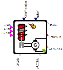
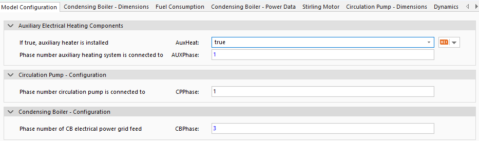
If the maximum heat generation of the boiler is not sufficient to cover the system heat requirement, the heat generation can be increased via an additional heating component. To do this, the AuxHeat parameter must be set to true and the boiler is then equipped with an additional heating element. After setting AuxHeat to true, the AUXPhase parameter can be used to set the phase type of the newly appeared ▶AUXGrid1 connector (1 = dc, 3 = ac). The connector ▶AUXGrid1 must then also be connected directly to a dc grid or to an ac grid with a phase tap.

Under the tab Condensing Boiler - Power Data must be the nominal heating power of the auxiliary heating system AuxHeatPower defined.

Finally, under the Dynamics tab, the time constant for the auxiliary heating system's response to the boiler starting or shutting down must be defined tAUX. This time constant tAUX works in the same way as tCP (see for more information).
3 Phase Connection
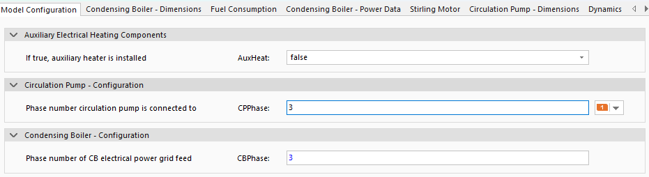
If the individual components of the heat pump have an ac connection, the number of phases for the individual components (CPPhase and optional AUXPhase) can be changed to 3, i.e. ac, in the Model Configuration tab.
Model Background
Fuel Utilization Efficiency
The parameters efficiency relating to net calorific value eta, relative latent heat LatentHeat, relative exhaust losses ExhaustLoss, and radiation losses RadiationLoss are used to calculate the system efficiency of the boiler
If there is no case-specific information available, use the pre-defined parameter sets:
Boiler Type | LatentHeat in % | ExhaustLoss in % | RadiationLoss in % | Resultant System Efficiency |
|---|---|---|---|---|
Constant temperature boiler | 6 | 10 | 20 | 66-70 |
Low temperature boiler | 6 | 6 | 1 | 88-93 |
Condensing boiler | 3 | 1 | 1 | 95-99 |
Fuel Power
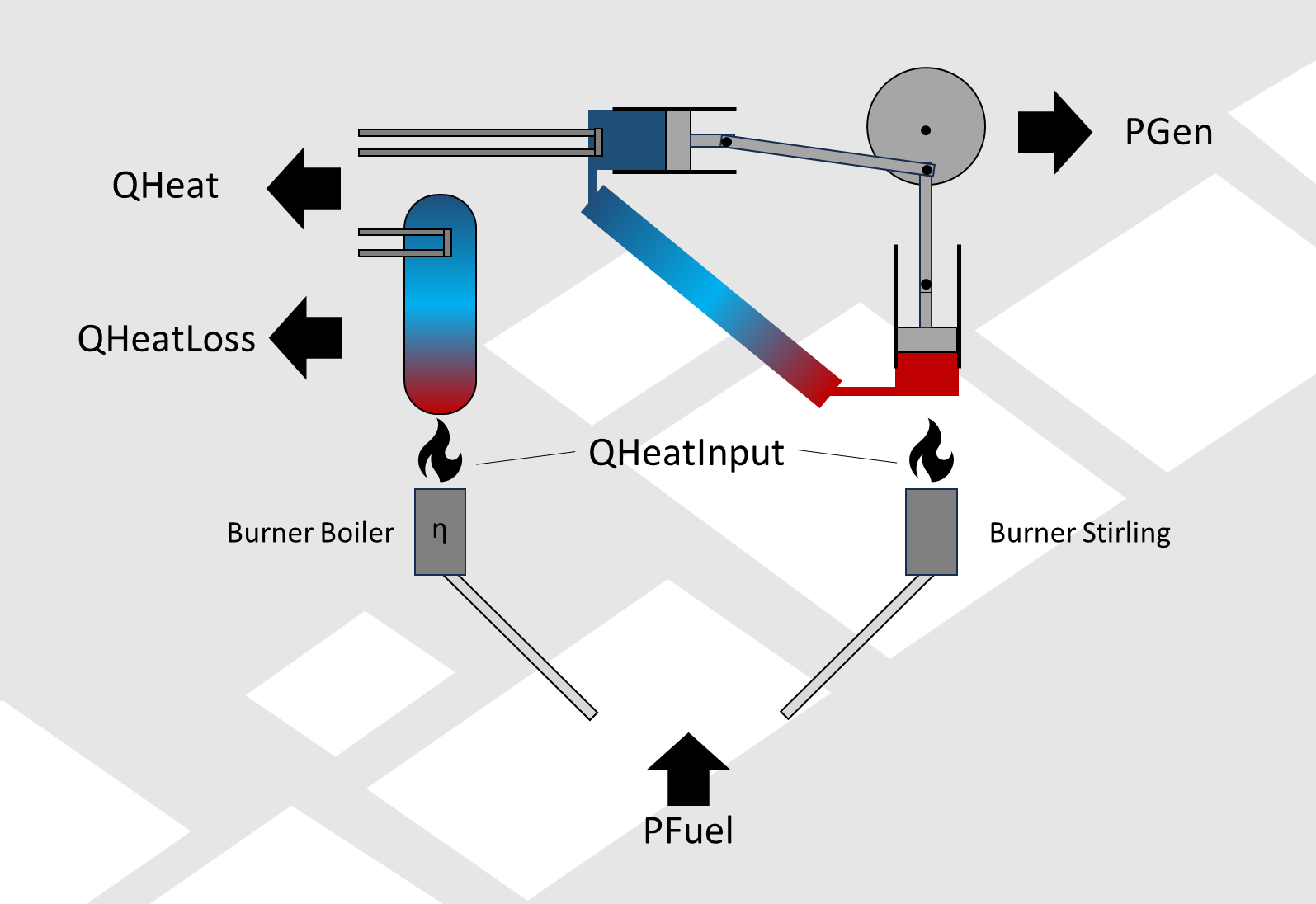
The fuel output within the CondensingBoilerStirling is calculated using the energy balance across the boiler and the stirling process. All relevant variables (QHeatInput, PGEN, and PFuel) are shown in the image above. The fuel output PFuel is used to drive the Stirling process, and if the thermal energy from the Stirling process is insufficient, the fuel output PFuel is also required to heat the boiler. This results in the individual components of the heat balance:
Fuel requirement of the boiler for providing the required heat QHeat
Heat input into the system QHeatInput corresponds to the current burner output
Usable heat output from the Stirling process
Fuel requirement for generating the Stirling process output
Combining the individual parts of the heat balance results in the lower overall equation for calculating the required fuel output PFuel to provide the required heat in the heat sink of the system QHeat.
Time Dynamics
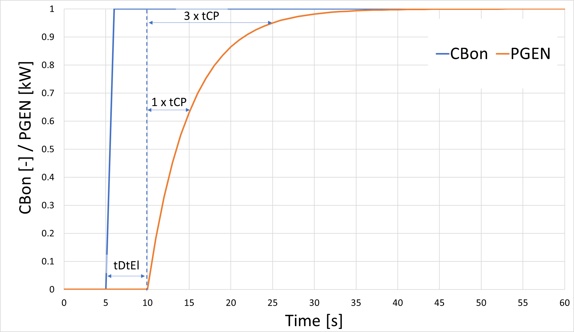
The times of the pumps and the CondensingBoilerStirling are modeled in the model via PT1 elements, whereby the entered parameters (e.g. tThStart and tCP) represent the time constant of the PT1 element and the dead time tDtEl is the time without any reaction of the model to changes in the controls. When the CondensingBoilerStirling is switched on, the electrical and thermal powers (e.g. PCP, PGEN, QHeat and PAux) increase according to the typical behavior of the step response of a PT1 element. This means that after once the time constant (e.g. tCP = 5s) the electrical and heating power rise to 63% of its original value, after twice the time constant (2 * tCP) to a value of 95% and after five times the time constant (5 * tCP) to 99.2%.