MicroWindTurbine
Symbol | 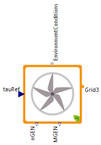 |
|---|
Use
Micro wind-turbines are renewable energy production systems which can be used to produce electrical energy utilizing wind energy. Note that the size of the micro wind-turbine does not effect the model usability. Therefore, small building-integrated wind-turbines and free-standing wind energy plants with higher nominal electrical power output can be modeled. The normal implementation of this model is however meant for smaller building-integrated systems. For the simulation of a wind power plant use the corresponding simulation model or for a wind power plant park.
Parameters and Connectors
The MicroWindTurbine has three connectors which are connected to external models. At first the target value for the electrical torque moment ▶tauRef must be connected to the controller of the micro wind turbine, the ▶EnvironmentConditions to the environment model and the ▶Grid3 to the ac grid.
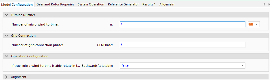
Under Turbine Number is the parameter number of micro-wind turbines n defined, which decides how many wind turbines are modeled. All other parameters will be noted down for one micro wind turbine data. Note that mutual influences on aerodynamic effects of several wind turbines cannot be simulated with the provided model. Within the Grid Connection, the number of phases GENPhase must also be defined to which the generator is connected. This is important to assess, if unsymmetrical electric loads occur in the grid. Currently, GENPhase is 3 and will give the wind turbine power for an ac connection. If GENPhase is set to 1 the connector ▶Grid1 appears and can be connected to a dc grid. If the MicroWindTurbine can rotate in two different direction set the value BackwardsRotatable to true else let the value at false. Usually, micro wind-turbines align themselves into the wind direction or only run in a single fixed direction. Due to this, the parameter BackwardsRototable should generally, be set to false. The functionality of reverse rotation is only implemented for academic research, in which its effect on electricity production can be of interest.
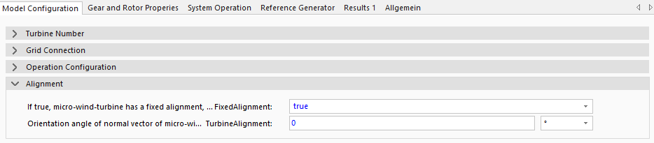
If the parameter FixedAlignment is true, then the MicroWindTurbine has always the same orientation angle TurbineAlignment (0° north, 90° east, 180° south, 270° west). Otherwise the TurbineAlignment is internally set to the wind direction and optimizes the wind usage.
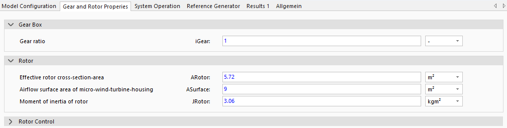
To define the gearbox and rotor parameters, adjust the values under Gear and Rotor Properties. For the gearbox, set the transmission ratio iGear, which can be left at the default value if no value is known. The rotor, on the other hand, requires the data from the data sheet for the effective rotor cross-section area ARotor, the airflow surface area of the micro wind turbine housing ASurface, and the moment of inertia of the rotor JRotor. Here, the two surface area parameters ASurface and ARotor are provided. For a free-standing wind energy plants the wind face area and the rotor surface area are equal. However, when modeling building-integrated turbines with special enclosures, the ASurface is most often larger than ARotor (for more details see the background).

It is additionally important to parameterize the rotor control mode PitchStall. Concretely, this describes how the rotors power production is reduced when wind speed exceeds nominal boundaries (vWindNominal under System Operation). If the parameter PitchStall is true, then the MicroWindTurbine is pitch controlled. This means that the rotor blades of the wind turbine are actively adjusted depending on the wind speed. If PitchStall is false, the rotor blades are controlled via a stall and remain stationary. Stall effects cause strong turbulences on the rotor blades resulting in reduced aerodynamic forces and thus a lower power production. Pitch-control on the other hand adjusts the angel of the rotor to the wind direction thus also reducing power production.
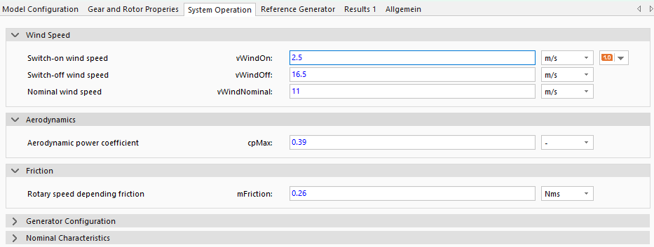
To control the MicroWindTurbine, the wind speeds at which the wind turbine is switched on or off (vWindOn and vWindOff) and the expected average wind speed (normal value) vWindNominal must be specified. To calculate the flow conditions, the aerodynamic power coefficient cpMax must be specified, which is a measure of the effectiveness of the conversion of kinetic wind energy into mechanical energy. The final value is the friction of the rotor, which is determined by the parameter mFriction. The provided friction coefficient mFriction is an adapting characteristic for the resultant generator speed dependent on the measured wind speed. This value represents a friction-dependent rotational speed and should thus be adapted by comparing the nominal wind speed and nominal generator speed, iteratively. In general, the generator should rotate with nominal generator speed at nominal wind speed. For all these parameters, if no exact values are known, the default values should be used.
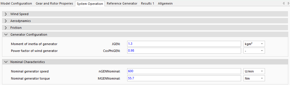
The generator parameters under System Operation are the moment of inertia JGEN and the power factor CosPhiGEN of the generator, as well as the nominal values of the generator for the rotational speed nGENNominal and the torque MGENNominal. These can be found in the data sheet for the wind turbine or generator.
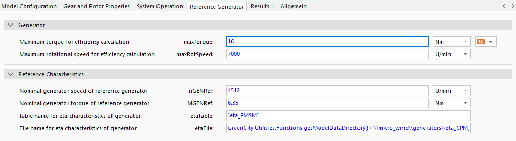
To limit the maximum torque maxTorque and the maximum rotational speed maxRotSpeed, these values must be taken from the data sheet of the wind turbine or generator and entered. Lastly, the reference generator characteristics must be defined. The resultant electric power output of a generator highly depends on the system efficiency. Generator efficiency is not constant, it varies dependent on generator speed and the torque (see etaTable under etaFile). To model these dependencies data of a 3 kW generator was used to define the efficiency characteristic of electric generators (see more details). This data is provided in the model data directory etaTable under etaFile. If other reference generator data should be used for simulation, use the corresponding data file as a template and adapt it. Generally, this is not needed as the efficiency characteristic of the provided reference generator is converted in the model to the parameterized generator (using the nominal values for modeled generator nGENNominal and MGENNominal and the reference generator nGENRef and MGENRef). That way it is possible to simulate special generator characteristics by only adapting the nominal generator properties nGENNominal and MGENNominal under System Operation to the model generator characteristics.
Model Background
Rotor Construction Type
Besides the definition of further gear box and rotor specifications it is important to describe the rotor construction type. Here, the two surface area parameters ASurface and ARotor are provided. For a free-standing wind energy plants the wind face area and the rotor surface area are equal. However, when modeling building-integrated turbines with special enclosures, the ASurface is most often larger than ARotor. In this case the resulting wind speed vWindResult (corrected by angle of incidence) is amplified compared to the wind speed vWind:
Reference Generator Characteristics
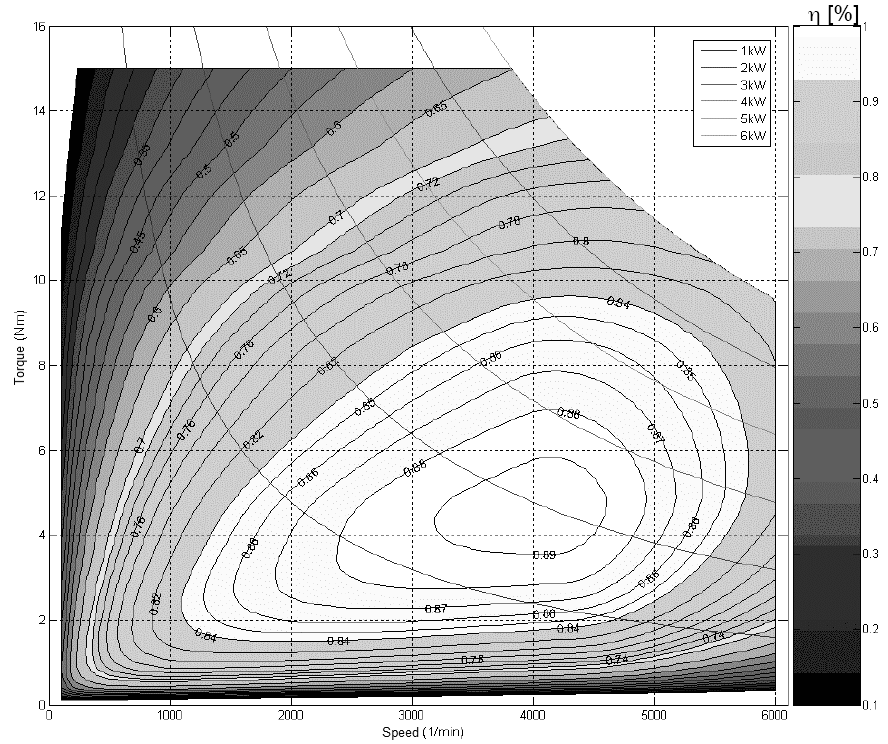
The picture above shows the internally used reference generator characteristics for efficiency dependent on generator torque and rotational speed.